


Can someone enlighten me please (Vibration absorbers)


Join Date: Feb 2002
Location: N20,W99
Age: 53
Posts: 1,119
Likes: 0
Received 0 Likes
on
0 Posts
Those are vibration dampers, and they are a good way to differentiate between the Mi-8 and Mi-17, amongst other things like the tail rotor on the opposite side, or the longer hump one of them has due to the pneumatic start versus the lead battery start on the older models.
How they work? I just know they are heavy and damp out vibration, same as in Bell 412, or Sikorsky's, Bo105's, someone else will know how to better explain this.
How they work? I just know they are heavy and damp out vibration, same as in Bell 412, or Sikorsky's, Bo105's, someone else will know how to better explain this.

Purveyor of Egg Liqueur to Lucifer
My guess is that it that this is a Mi-17-1/2 export variant with its mast-mounted vibration absorber.
SS
SS
Thread Starter
I did know about the differences you gave, but i didn't know that those dampers are also one of them. This damper is from a Mi-14PL, naval version, tail rotor on the left.
I only saw this damper on Mi-8MTV and this Mi-14.
I only saw this damper on Mi-8MTV and this Mi-14.
Purveyor of Egg Liqueur to Lucifer
A few more examples.


Join Date: Nov 2004
Location: Cambridgeshire, UK
Posts: 1,334
Likes: 0
Received 0 Likes
on
0 Posts
Never seen this before....
If it works anything like the torsional dampers fitted to engines, then they work like this:
The mass of the dampers acts like a flywheel (i looked hard, but they all seemed to be connected together). The flywheel is connected to the top of the rotor shaft by a torsional spring. The frequency of the flywheel/spring system is chosen to be the same as the main frequency of concern in the rotor drive system. This will be a torsional mode, and could be free power turbine mass twisting drive shaft against rotor mass, or a particular blade mode that the designers were trying to avoid.
When the drivetrain resonance rears its head, the damper becomes excited. In this way the modal energy is transferred into the damper. Normally the torsional spring is an elastomeric rubber, with a high level of hysteresis. The practical upshot is that the drivetrain seldom gets into a resonance, which prolongs the time-life of the entire drivetrain (worst case for drivetrain resonance is low cycle fatigue failure).
Hmmm, Powertrain dynamics - theres an interesting area...
Mart
Join Date: Apr 2003
Location: USA
Age: 75
Posts: 3,012
Likes: 0
Received 0 Likes
on
0 Posts
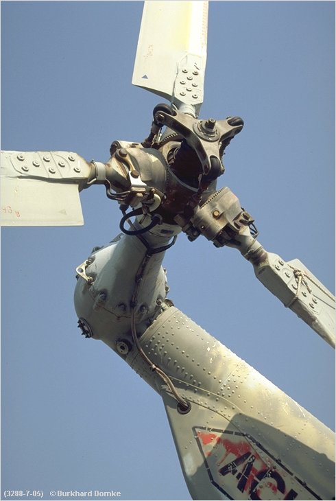
Graviman has it almost right. Those are in-plane vibration absorbers, similar to the Bifilar used on Sikorsky helicopters. The free weights are inside the yellow covers in the photo, and are not connected to each other. The covers keep ice and dirt away from the weights. The weights are held in place with bearings that let them swing about the arms, so that they are pendular in motion.
They are normally tuned to absorb the 5 per rev (5R) vibrations that the rotor sends to the fuselage.
The weights are held in the CF field by the rotation, so they act as though they are on springs, and oscillate about their bearings. They resonate at the 5 per rev frequency so they can efficiently absorb the vibrations that the blades give the head.
Here is a close-up:
http://www.b-domke.de/AviationImages...head/3828.html
Here is a shot of a Sea Hawk head, where the weights are exposed and the bearings can be seen:
http://www.b-domke.de/AviationImages...head/1642.html
Phoinix
Looking at four Mil8-MTV's right now here in Tajikistan. One with particle sep, 3 without. Interstingly, none of them have the Vibration Absorber fitted. Might only be MTV-1 that has it fitted, and -17.
noooby
Looking at four Mil8-MTV's right now here in Tajikistan. One with particle sep, 3 without. Interstingly, none of them have the Vibration Absorber fitted. Might only be MTV-1 that has it fitted, and -17.
noooby
Join Date: Nov 2004
Location: Cambridgeshire, UK
Posts: 1,334
Likes: 0
Received 0 Likes
on
0 Posts
Ah OK. That makes sense...
Thanks for putting me right, Nick. Learn something new every day. 
Is this a problem that is particular to these 5-bladed articulated, or are 1P modes something that bugs every new design? I imagine that the other way of solving it is hydromounting the gearbox, to isolate the fuselage from all rotor dynamic vibration.
Out of interest have you found that the rotor dynamics guys get it right on a new design, or would this normally be an area reserved for flight testing (rotation order frequency plots, etc)? My reading of both Prouty and Newman (Westland) indicated to me that while the cause of 1P,2P,3P, etc was generally understood, the magnitude of these was normally only determined once the first machine was flying (although i imagine some whirl tower dynamics would also be used).
(Ahhh - If i had a vast cash reserve i would while away the hours thinking about physics, designing engines and flying helicopters") )
)
Mart
Is this a problem that is particular to these 5-bladed articulated, or are 1P modes something that bugs every new design? I imagine that the other way of solving it is hydromounting the gearbox, to isolate the fuselage from all rotor dynamic vibration.
Out of interest have you found that the rotor dynamics guys get it right on a new design, or would this normally be an area reserved for flight testing (rotation order frequency plots, etc)? My reading of both Prouty and Newman (Westland) indicated to me that while the cause of 1P,2P,3P, etc was generally understood, the magnitude of these was normally only determined once the first machine was flying (although i imagine some whirl tower dynamics would also be used).
(Ahhh - If i had a vast cash reserve i would while away the hours thinking about physics, designing engines and flying helicopters
Mart
Join Date: Apr 2003
Location: USA
Age: 75
Posts: 3,012
Likes: 0
Received 0 Likes
on
0 Posts
Graviman,
The natural vibration that we see at N per revolution (where N is the number of blades) is a product of the fact that each blade is delivering a chunk of the lift. The more blades, the more (and smaller) chunks and the less N per Rev that the rotor delivers to the aircraft, so a 5 bladed rotor has less natural vibration than one with fewer blades.
Generally, large transports need more vibe solutions not because the rotor puts out more vibration, but because the bigger fuselages with larger spans across and along the cabin create more susceptability to an adverse reaction to the naturally imposed vibration. In other words, bigger things shake more easily at the typical frequencies (think of a diving board, the longer it is the very much lower the natural frequency is, and the more likely it will react to a disturbing vibration.)
1 per rev is not helped or cured by the bifilar, only N per Rev.
Here is what I posted previously when a question about Black Hawk bifilars came up:
I helped develop the bifilars on two of our models, and understand them a bit:
They are simple swinging masses that are resonent near the N/rev frequencies (4 per revolution in the Black Hawk and S-76)- they love to hum along at the same beat frequency as the blade passages. They are actually tuned to N-1 and N+1 because they are in the rotating system, where the blade passage frequency is made up of the sum of those two frequencies.
The bifilar is much lighter than other vibration absorbers, and right at the source. Also, there is no spring on a bifilar, they achieve their frequency by CF, so they automatically tune to the rpm they are at, allowing large rpm changes without large vibration changes.
Bifilars work in-plane, the most effective direction. Generally, if only one is needed, the one bifilar is tuned to 3 per rev (N-1) which is the bigger, more objectionable component. Nobody removes bifilars by themselves, because they are part of the airworthiness of the machine, not an option. The vibrations at many airframe stations, not just the people, depend on them, so just tinkering with them might make some nice piece of equipment very sad without showing up on the normal maintenance gear. We want our engines to be very very happy, don't we?
Bifilars were invented for piston engines decades ago, and are not rocket science.
The orientation of the arm over the space between the hub arms is specifically designed to allow ease of maintenance and to prevent interference with blade flapping. There is no issue with the exact orientation, the weights all act to absorb the in-plane vibrations.
The only vibration they act on is N per rev. NO other frequency is helped by the bifilar. If one weight is badly slung, and does not swing properly, some odd frequencies can be flet, because the other weights conspire to upset the vibration balance. Typically, a 3 per rev is felt if the bifilar is badly maintained.
Join Date: May 2005
Location: Europe trying to enjoy retirement �YES�
Posts: 372
Likes: 0
Received 0 Likes
on
0 Posts
Igor was a clever chap and the Bifilars are a cool way of correcting for the change of disk c of g with cyclic changes to disc path plane on the S61 and S76. Bell has used a similar method with the pendulum dampers on the 412. All works well as long as the lateral movement on the bearings is kept to a minimum. Hint to 412 drivers look out for brunelling(?) on the needle bearings during preflight inspections.
Outhouse
Outhouse
Join Date: May 2005
Location: Europe trying to enjoy retirement �YES�
Posts: 372
Likes: 0
Received 0 Likes
on
0 Posts
Thanks for the addition to the thread PhilJ, I was unsure regarding spelling thus I included the? I will add to my dictionary and hope to perform better regarding spelling bees.
As a friendly extension to the discussion regarding the subject would anyone like to suggest a formula that enables the calculation to achieve maximum effect? Hint rotor speed X.
To 412 drivers, what would be the effect of lateral movement on the damper weights and or any brinelling on the needle bearings?
Join Date: Apr 2003
Location: USA
Age: 75
Posts: 3,012
Likes: 0
Received 0 Likes
on
0 Posts
outhouse,
The vibrations that the blades deliver to the head have nothing to do with CG effects due to flapping. The dynamics of how stuff vibrates is complex, but understandable in a sense.
The cg effects are tiny, it is the aerodynamic force and the response of the blade as a structure that tell the story. Every diving board has a natural frequency, as does each tile on a xylophone. The way these vibrations arise is due to the tuning of the blade and head response to the fuselage response.
Join Date: Apr 2003
Location: Vancouver, BC, Canada
Posts: 1,635
Likes: 0
Received 0 Likes
on
0 Posts
Join Date: Nov 2004
Location: Cambridgeshire, UK
Posts: 1,334
Likes: 0
Received 0 Likes
on
0 Posts
Ah, i get it!
Blimey! It took the combined talents of Prouty, Newman, Lappos, and Jackson to shove it into my brain - but i got it...
In forward flight, as the blade sweeps out it's path, each position of each blade is subject to varying angles of attack and sweep from the ingested air. The fast revolution of the rotor means that these forces likely excite all of the blade fundamental resonances. Additional vibration sources exist in the form of the varying profile (and to a lesser extent induced) drag through azimuth, and any manouvreing input (particularly for an articulated hub). This inevitably leads to the hub suffering input forces with fundamental harmonic of Np. Higher harmonics also exist, but are less in magnitude (and may be trimmed out with Higher Harmonic Control).
The bifilars are basically just pendulums with clever mechanisms for a compact geometry (using centripetal accel). They are no good if tuned to Np since the pendulums on (say) the advancing and retreating sides of the rotor would "wobble" in phase relative to rotor rotation, but out of phase with repect to airframe, thus cancelling any fore-aft force. By tuning them all to either Np+1 or Np-1 then you ensure that bifilars on (say) the advancing and retreating sides "wobble" out of phase wrt to rotor rotation, but in phase wrt to airframe fore-aft direction. This means that both go forwards and backwards together at just the right frequency to cancel the rotors Np fore-aft wobble - and likewise for sideways wobble.
In laymans terms:
System behave like a dod of metal on the end of a spring, tuned to Np...
Mart
[Edit: To rephrase first paragraph in accordance with Nick Lappos' subsequent posts]
Last edited by Graviman; 31st Jul 2005 at 23:35.
Join Date: Apr 2003
Location: USA
Age: 75
Posts: 3,012
Likes: 0
Received 0 Likes
on
0 Posts
Graviman,
Your second paragraph about the weights rotating in a centrifugal field as if by spring force is right on!
The first paragraph however is still hanging onto some idea that the N per revolution is due to a blade movement/mass balance issue, which is not correct. It is funny how mechanical engineers see the mechanism, but not the air! The blades go from upwind at Mach .9 to downwind at near stall. They see flipping and shoving by tons of air per minute, and are constantly ringing at their natural frequencies as the loading on them shifts with the air's forces. They attempt to average out 1 x the aircraft's weight while doing these gymnastics.
This creates a natural N/Rev vibration, (N+1 and N-1 in the rotating field) that shakes the aircraft.
Why is it not blade motion? Two proofs: 1) The max flapping occurs highest in many aircraft in level flight at 40 knots, but peak N/rev is usually (always) at max speed.
2) Rigid rotors with the least flapping motion have the highest N/rev!
Join Date: Nov 2004
Location: Cambridgeshire, UK
Posts: 1,334
Likes: 0
Received 0 Likes
on
0 Posts
Nick,
Good point well made. The use of compliance to explain the force input was not the best approach.
Mech heads just see the world in terms of things they can affect. Air is that viscousy stuff that you need to heat to make engines whirr, and throw at the ground to make aircraft whizz...
Mart
[Edit: Shpelleeng]
Last edited by Graviman; 28th Jul 2005 at 15:36.