


Jet thrust

Thread Starter
Join Date: Nov 2007
Location: Yorkshire
Age: 36
Posts: 66
Likes: 0
Received 0 Likes
on
0 Posts
Jet thrust
Hi there,
I wonder if someone could help to consolidate my knowledge regarding how a jet engine creates propulsion.
Every piece of text that I have read on the subject regurgitates Newton's second and third laws as explanations for the production of thrust ('f = ma' and 'every action has an equal and opposite reaction'). In the simplest terms, shooting air rearwards imparts a force (thrust) on the engine which is equal and opposite to the force that shot the air backwards in the first instance.
This explanation is fine for a propeller or the outer part of a turbofan disc that propels bypass air whereby something hard is physically exerting a force on the air to accelerate it. My problem is that the core of a jet engine essentially accelerates air through combustion and expansion - I'm having difficulty in defining the 'action' and locating the (presumably co-incident) points of action and reaction within the gas generator.
D P Davis' 'Handling the Big Jets' states that "the thrust of an aircraft propulsive system is the reaction to the force required to accelerate a mass of air through the system, and is manifested as pressure forces . . . . . on all internal surfaces in the case of a jet engine". This is the only reference that I've seen which actually says that components within the engine experience a physical propulsive force. This helps my understanding to a degree but it also raises two questions:
Many thanks and best regards to you all.
I wonder if someone could help to consolidate my knowledge regarding how a jet engine creates propulsion.
Every piece of text that I have read on the subject regurgitates Newton's second and third laws as explanations for the production of thrust ('f = ma' and 'every action has an equal and opposite reaction'). In the simplest terms, shooting air rearwards imparts a force (thrust) on the engine which is equal and opposite to the force that shot the air backwards in the first instance.
This explanation is fine for a propeller or the outer part of a turbofan disc that propels bypass air whereby something hard is physically exerting a force on the air to accelerate it. My problem is that the core of a jet engine essentially accelerates air through combustion and expansion - I'm having difficulty in defining the 'action' and locating the (presumably co-incident) points of action and reaction within the gas generator.
D P Davis' 'Handling the Big Jets' states that "the thrust of an aircraft propulsive system is the reaction to the force required to accelerate a mass of air through the system, and is manifested as pressure forces . . . . . on all internal surfaces in the case of a jet engine". This is the only reference that I've seen which actually says that components within the engine experience a physical propulsive force. This helps my understanding to a degree but it also raises two questions:
- Why does force on all internal components equate to thrust? Shouldn't only the forces that act on the internal surfaces that are perpendicular to the engine's longitudinal axis be of significance?
- Shouldn't only the components that provide the mystery force that accelerates the air experience the reaction force? If so, we go back to the conundrum of defining the 'action' and relating this to combustion and expansion.
Many thanks and best regards to you all.

This isn't definitive but it is my take on the process:
Imagine a sealed cylinder containg a fuel air mix at ambient pressure. The mixture is ignited and the contents of the cylinder are now at much higher pressure. This pressure is exerted evenly on the inside of the container in every direction. So no net thrust.
Now imagine one end of the cylinder is suddenly removed. In the instant it takes the pressure to equalise, the pressure on the opposite (remaining) end of the cylinder has no balancing force at the other (now missing) end. Therefore the cylinder has net thrust in one direction.
A jet engine manages to maintain this state of a pressurised container that is open at one end. It does this by virtue of having a compressor instead of the closed end.
Logically the thrust-force must be applied at each rotor/stator stage because it is across these stages that the pressure differential is. So ultimately, in a sense, similar to propeller or fan thrust.
This view satisfies my own "Newtonian" instincts. No doubt it will have aerodynamycists screaming in outrage at their computer screen, and thermodynamycists will sob quietly whilst banging their foreheads gently on the desk.
Last edited by Dont Hang Up; 1st Feb 2012 at 15:05.
Join Date: Jan 2012
Posts: 38
Likes: 0
Received 0 Likes
on
0 Posts
Your analogy of the jet engine being a pressurised cylinder with an opening at one end was helpful.
Lorin's article in the journal "L'A�rophile"
Join Date: Jan 2012
Location: Ontario
Age: 74
Posts: 82
Likes: 0
Received 0 Likes
on
0 Posts
thrust calculation
bravobravo74
In case you are still on the lookout for any more info the book 'The Jet Engine' by Rolls-Royce, has a chapter on thrust distribution and shows that the thrust on each component, eg compressor, combuster, final nozzle, etc, comes from 2 main components, a pressure force due to static pressure difference and a momentum force due to change in axial momentum.
All the contributions feed either through the rotor thrust bearings or directly into the fixed structure.
The calculation above does a whole component as one, eg a complete LP turbine, rotor blades and fixed nozzles, whereas as far as the engine is concerned the loads are split up and the blade thrust is netted with the fan thrust before going through the thrust bearing.
Even when there is no energy transfer there is still a thrust as in ducts and final nozzles of course. With ducts their function is to slow down the air to reduce pressure losses so there is still a difference in static pressure force and momentum between entry and exit.
Last edited by peter kent; 1st Mar 2012 at 00:15. Reason: add words
Join Date: Sep 2007
Location: Dubai
Age: 67
Posts: 4
Likes: 0
Received 0 Likes
on
0 Posts
Jet engine thrust
I have had similar problems in verifying where jet engines actually generate their thrust. Most Internet sources, including YouTube, seem to state (unhelpfully) that the thrust is generated because the exhaust gases exit faster than the intake air.
But my understanding is that once you net out the forces, the majority of the thrust is generated in the compressor stages (turbojet, not HBR turbo fan) because that is where the "machinery", as it were, is pushing air backwards and hence, by reaction, is experiencing a forward driving force.
The turbine, by contrast, has a rearward gas load - it is being pushed backwards, against the direction of motion. Even the tail pipe, tapering toward the rear, experiences a rearward load. I believe there is some residual thrust in the exiting gases (presumably "pushing" against the rear bearing and the back of the LP turbine) but it is only a few percent of the total thrust.
The problem I have with the seemingly wrong explanations I hear is that some of the proponents have no problem agreeing that in a turbofan setup the fan, driven by the LP turbine, produces most of the thrust, whereas in a pure turbojet in which the compressor, also driven by the turbine, is doing the same thing i.e. moving air backwards, it is somehow not contributing to thrust. It can't be so.
And given that the job of the turbine is to extract as much energy as possible from the hot gas stream and to convert it into useful work, of course there is very little energy left in the exhaust gases to provide thrust. That is the whole idea.
So - at the risk of using non-scientific concepts - as far as I can see, the jet engine simply "sucks" the plane forwards due to the huge pressure differential created across the whole engine, and concentrated in the compressor stages.
Am I completely mad? I'm certainly going mad trying to discern the truth among the confusing explanations, some of which come from none other than GE and Rolls Royce. Does anyone in the Forum know about this for sure?
Explanations are dependent on the ears that hear them. What works in this forum may fall flat in a pub or afternoon tea.
Every perpendicular surface has a pressure balance across it. Some forward and some rearward in a jet engine. If you can keep the air moving through the engine fast enough you can managed to get an overall pressure balance pushing forward.
This requires energy in the form of heat to be added.
(if the engine itself is moving through the air some other pressure balances need be considered) Time for another beer
The following is from the Rolls Royce jet engine book and shows the typical gas loads. Some are thrust and some are drag, the net thrust in this example being 11,158 pounds.

Join Date: Dec 2007
Location: Bath
Age: 71
Posts: 92
Likes: 0
Received 0 Likes
on
0 Posts
I'm not an engine person myself, but was interested enough to book out a set of engine trade AP's when in the RAF.
I do recall seeing the forward & rearward gas loads being shown for an Avon jet engine. Interestingly, the reheat diagram showed a reduction in the exit nozzle rearward load when lit, no extra forward load being produced.
I'm not sure whether this is the case with all reheat systems, reducing the rearward gas load, without adding a forward gas load.
As Lomapaseo has said �Explanations are dependent on the ears that hear them. What works in this forum may fall flat in a pub or afternoon tea.� It is very easy to take well established laws and use them to deduce completely incorrect answers.
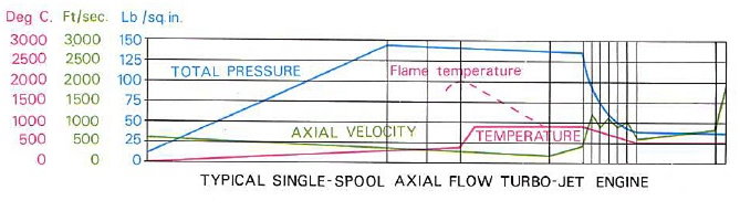
Readers who have time to spare and curious dispositions might like to look at the diagram provided by Megan and consider the following:
It is a well established principle of jet engine design that the axial velocity of the airflow exiting the compressor rear face will be approximately the same as that entering the front face. Velocity will increase in the rotors and decrease in the stators, but overall there will be little change. Megan�s diagram show a thrust force of 19049 lbs being generated by the compressor. If the compressor does not accelerate the air rearwards how does it produce this thrust?
The diffuser is a divergent duct and the air passing through it is sub-sonic. It is a well established fact that when sub-sonic flow passes through a divergent duct, its velocity decreases. But Megan�s diagram shows a thrust of 2186 lbs being generated in this area. Newton�s second law predicts that because the velocity of the air is decreasing (negative acceleration) the force should act rearwards. Why does it not do so and what is producing the thrust force?
It is a well established fact of jet engine design that when the gasses flow through the turbines their axial velocity increases. We are accelerating the gas rearwards, so according to Newton�s second law we should be producing a forward thrust force. But Megan�s diagram show a rearward force of 41091 lbs. Why does this force appear to be defying Newton?
The propelling nozzle is a convergent duct and the gas velocity passing through it is sub-sonic. According to Newtons second law this should produce a forward acting thrust force. But Megan�s diagram shows a rearward force of 5587 lbs. Once again our engine appears to be defying Newton. It is a generally accepted fact that the purpose of the propelling nozzle is to increase the thrust. But as Megan�s diagram shows, the axial force acting on this nozzle is rearwards. If we were to suddenly release the nozzle in flight it would be blown rearwards. So how is the propelling nozzle increasing the thrust.
Although I have used the term �Megan�s diagram� repeatedly in this post, this is not intended to be any form of criticism of Megan. The diagram was produced by Rolls Royce and is factually accurate.
Join Date: Dec 2007
Location: Bath
Age: 71
Posts: 92
Likes: 0
Received 0 Likes
on
0 Posts
Well, something is pressing on the metal somewhere & the Rolls Royce diagram, though very helpful, could have been split up into more detailed portions.
The 'Pressing on the metal' does very though, in different flight conditions.
I asked a somewhat similar question on this forum quite some time ago, about the possibility of the exit nozzle sticking open when in non reheat.
One gets a reduced thrust in that condition, even though the rearward gas load on the nozzle is no longer there.
I received a very helpful reply (Can't remember from who) saying that the fuel control unit will sense an over speed engine condition & reduce fuel supply to the engine.
I understand that it's a question of matching the exit nozzle area, with the upstream turbo machinery.
I do remember seeing tabs of metal riveted to the end of the jet pipe on Strikemasters (Jet Provosts) called 'Trimmers' the idea being to get an exact trim on the nozzle area.
So yes, a much more detailed diagram would be very helpful.
Same with convergent/ divergent ducts, show us exactly what's pressing on the metal!
I'm no expert on this, but my interpretation of the diagram posted by Megan is:
On the losses side:
On the losses side:
- 41091lb represents the work done by the turbine in driving compressor.
- 5587lb is the loss of thrust (work done) by converging the jet efflux.
- 19049lb of suction (as per your vacuum cleaner) from the compressor sucking in air
- 2186lb of push on the back of the compressor from the air expanded by the fuel burning
- 34182lb of thrust by the expanded air being pushed out the back of the combustion cans
- 2419lb of push on the back of the turbine from the air expanding in the jet pipe
Last edited by Mechta; 29th Jun 2015 at 21:38.

PPRuNe Handmaiden
Not to take any thing away from the discussion above, I just think of an inflated balloon and what happens when you let go. I am a firm believer of KISS and PFM - although, that won't help with deciding "A, B, C or D" in the exam. 

Join Date: Sep 2007
Location: Dubai
Age: 67
Posts: 4
Likes: 0
Received 0 Likes
on
0 Posts
Thrust distribution in stages
Check out this link
https://books.google.ae/books?id=ubJ...engine&f=false
Where the different stages are calculated in turn. I think I have my answer, or at least a better grasp of the subject. Thanks to all who contributed on the forum too.
https://books.google.ae/books?id=ubJ...engine&f=false
Where the different stages are calculated in turn. I think I have my answer, or at least a better grasp of the subject. Thanks to all who contributed on the forum too.
