


Lightning

Thread Starter


Joined: Feb 2006
Aviation Qualifications: LAME
Posts: 36,145
Likes: 5,739
From: Falling off the end of the thread
Lightning
At Bruntingthorpe for those that missed it.
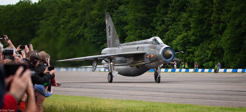
Smile please.. by Tony Taylor, on Flickr

Lightning Run by Tony Taylor, on Flickr

Lightning Run 2 by Tony Taylor, on Flickr

Lightning return by Tony Taylor, on Flickr
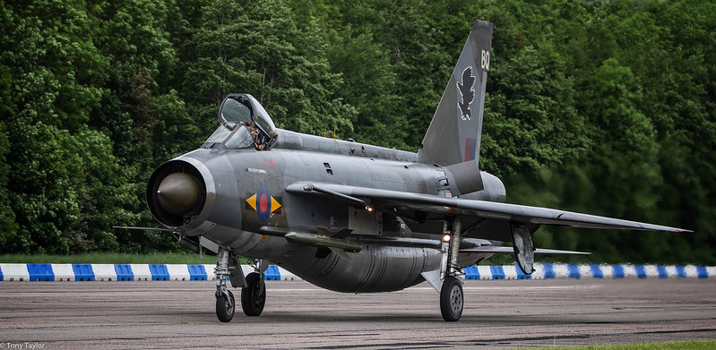
Lightning open canopy by Tony Taylor, on Flickr
Smile please.. by Tony Taylor, on Flickr
Lightning Run by Tony Taylor, on Flickr
Lightning Run 2 by Tony Taylor, on Flickr
Lightning return by Tony Taylor, on Flickr
Lightning open canopy by Tony Taylor, on Flickr


Joined: Aug 2007
Posts: 1,139
Likes: 55
From: virginia, USA
Thank you for posting. Would really love to get there someday.
Why do the first three photos look like there is a plug in the intake? Is that condensation under certain atmospheric conditions/engine RPM? Common?
Why do the first three photos look like there is a plug in the intake? Is that condensation under certain atmospheric conditions/engine RPM? Common?
Joined: Jan 2006
Posts: 190
Likes: 33
From: London
The video doesn't do justice to the volume of low frequency noise which just resonates through your whole body. Fantastic day, with the VC10, Comet, Beluga and Shack all open to visit the cockpit. Unfortunately couldn't stay to see the Victor do its run.
Last edited by topgas; 30th May 2019 at 15:09.
Thread Starter
Joined: Feb 2006
Aviation Qualifications: LAME
Posts: 36,145
Likes: 5,739
From: Falling off the end of the thread
Joined: Jul 2001
Posts: 803
Likes: 14
From: Darwin, NT, Australia
I had the opportunity to sit in the Lightning cockpit at Tangmere this week.
I quickly realised that that it was not designed for oversized colonials. It was tighter than the SE5 mock up they have.
Such a small office for such a large airframe. My respect to those of you who mastered her.
I quickly realised that that it was not designed for oversized colonials. It was tighter than the SE5 mock up they have.
Such a small office for such a large airframe. My respect to those of you who mastered her.
Thread Starter
Joined: Feb 2006
Aviation Qualifications: LAME
Posts: 36,145
Likes: 5,739
From: Falling off the end of the thread


Joined: Sep 2004
Posts: 2,141
Likes: 331
From: Royal Berkshire


Joined: Oct 2017
Posts: 4
Likes: 0
From: UK
The "condensation" in the intake is simply explained.
The radar bullet forms a convergent duct initially. This results in flow acceleration which causes a drop in pressure and therefore a drop in temperature.
When the relative humidity is high this temperature drop causes saturation and thus visible moisture. Seemples.
The radar bullet forms a convergent duct initially. This results in flow acceleration which causes a drop in pressure and therefore a drop in temperature.
When the relative humidity is high this temperature drop causes saturation and thus visible moisture. Seemples.
Ecce Homo! Loquitur...

Joined: Jul 2000
Aviation Qualifications: Spotter
Posts: 24,695
Likes: 7,377
From: Peripatetic
https://www.skytamer.com/English_Ele...tning_F.6.html
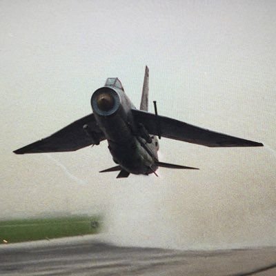
“Supersonic speeds also threatened inlet stability; the inlet's central shock cone served as a compression surface, diverting air into the annular inlet. As the “Lightning” accelerated through Mach 1, the shock cone generated an oblique shock positioned forward of the intake lip; known as a subcritical inlet condition, this is stable but also produces inefficient spillage drag. Around the Design Mach speed, the oblique shock is positioned just in front of the inlet lip and efficiently compressed the air without any spillage. As speed increases beyond Design Mach, the oblique shock becomes supercritical, where supersonic airflow enters the inlet duct. The “Lightning's” inlet was designed to handle only subsonic air, a supercritical state not only drastically reduced engine thrust output but could lead to surges or a compressor stall, which could result in engine flameout and/or damage.
Thermal and structural limits were also present; as air is heated up when compressed by the passage of an aircraft. This heating increases considerably when at supersonic speeds. The airframe absorbs heat from the surrounding air, the inlet shock cone at the front of the aircraft becoming the hottest part. The shock cone was composed of fiberglass, necessary because the shock cone also served as a radar radome; a metal shock cone would interfere with the AI 23's radar emissions. The shock cone would be eventually weakened due to the fatigue caused by the thermal cycles involved in regularly performing high-speed flights. At 36,000 ft and Mach 1.7, the heating conditions on the shock cone would be similar to those at Sea Level and 650 KIAS, but if the speed was increased to Mach 2.0 at 36,000 ft, the shock cone would be exposed to temperatures more than 70% higher than those at Mach 1.7. The shock cone was strengthened on the later “Lightning” F.2A, F.3, F.6, and F.53 models, thus allowing routine operations at up to Mach 2.0.”.....

Joined: Oct 2017
Posts: 4
Likes: 0
From: UK
Yes - I know, having flown it for five years.
That's not what the question was about though.
Is the web your friend ?=left
That's not what the question was about though.
Is the web your friend ?=left
=leftSupersonic speeds also threatened inlet stability. The inlet's central shock cone served as a compression surface, diverting air into the annular inlet. As the Lightning accelerated through Mach 1, the shock cone generated an oblique shock positioned forward of the intake lip. Known as a subcritical inlet condition, this was stable, but produced inefficient spillage drag. Around the Design Mach speed, the oblique shock was positioned just forward of the inlet lip and efficiently compressed the air without spillage. When travelling beyond the Design Mach, the oblique shock would become supercritical, and supersonic airflow would enter the inlet duct, which could only handle subsonic air. In this condition, the engine generated drastically less thrust and may result in surges or compressor stalls, these could cause flameouts or damage.=leftThermal and structural limits were also present. Air is heated considerably when compressed by the passage of an aircraft at supersonic speeds. The airframe absorbs heat from the surrounding air, the inlet shock cone at the front of the aircraft becoming the hottest part. The shock cone was composed of fibreglass, necessary because the shock cone also served as a radar radome; a metal shock cone would interfere with the AI 23's radar emissions. The shock cone would be eventually weakened due to the fatigue caused by the thermal cycles involved in regularly performing high-speed flights. At 36,000 feet (11,000 m) and Mach 1.7 (1,815 km/h), the heating conditions on the shock cone would be similar to those at sea level and 650 knots (1,200 km/h) indicated airspeed,[nb 8] but if the speed was increased to Mach 2.0 (2,136 km/h) at 36,000 feet (11,000 m), the shock cone would be exposed to higher temperatures[nb 9] than those at Mach 1.7. The shock cone was strengthened on the later Lightning F.2A, F.3, F.6, and F.53 models, thus allowing routine operations at up to Mach 2.0.[85]
Joined: Aug 2007
Posts: 1,139
Likes: 55
From: virginia, USA
Thank you everyone for the explanation and that is a cracking picture GeeRam, and good piece on the inlet design ORAC- Lightning aerodynamics and design peculiarities are always a great topic of banter.
Thread Starter
Joined: Feb 2006
Aviation Qualifications: LAME
Posts: 36,145
Likes: 5,739
From: Falling off the end of the thread
The �Lightning's� inlet was designed to handle only subsonic air
