


Pitot Tube Question

Thread Starter
Joined: Jul 2006
Posts: 27
Likes: 0
From: Ireland
I was asked the other day by a very experienced aviator about pitot tube design. Not wanting to make a fool of myself, I said I'd research this...
He asked about the right angle that is almost always evident in pitot tube designs. From a physics perspective (not engineering / aircraft system design perspective), does there always have to be a 90 degree bend in the pitot tube?
I reckoned there doesn't have to be, but that it is included purely as a design consideration.
Anybody know the answer?

Joined: Sep 2004
Posts: 698
Likes: 0
From: Australia
Hey, Alpha Laura! 
I found this web site:
Pitot Tubes
and got lost about three words into it.
Good luck!
I found this web site:
Pitot Tubes
and got lost about three words into it.
Good luck!
Joined: Jun 2007
Posts: 24
Likes: 0
From: Ireland
The Pitot Tube is located away from the aircraft skin so as to remove it from the aircrafts "boundary layer".
The boundary layer is the layer of air between the surface and the free stream velocity in which local retardation takes place. Like the main airflow, the boundary layer flow can be either laminar or turbulent in nature.
In order for the Pitot tube to then face the oncoming airflow it is angled (roughly 90degrees)
I think thats the answer you are looking for.

Joined: Feb 2005
Posts: 4,581
Likes: 0
From: flyover country USA
On SE propeller aircraft, you have to move the pitot-static probe outside the propwash, and this is a typical WWII vintage Kollsman probe:
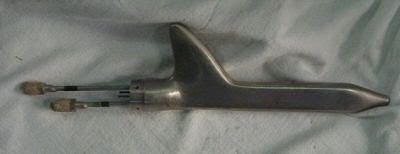
It was generally on a boom protruding 1/3 to 1/2 chord ahead of the wing LE.
The pitot and static lines were routed up through the "fin" - probably as a water trap.
It was generally on a boom protruding 1/3 to 1/2 chord ahead of the wing LE.
The pitot and static lines were routed up through the "fin" - probably as a water trap.
Thread Starter
Joined: Jul 2006
Posts: 27
Likes: 0
From: Ireland
Thanks for the replies
kiwi chick - eeesh, nice reading! Still trying to find the pictures they are referring too - I could maybe make sense of it then.
Andy - That wasn't entirely what I meant though. I was more concerned with the physics of what happens inside the pitot tube. Does the 90 degree bend help the measurement of flow by scaling down the rate of flow, or does it have a negligible affect on the flow parameters?
barit1 - *nodnod* But, what do you mean by water trap?
Joined: Mar 2002
Posts: 1,095
Likes: 166
From: South West
No requirement for a 90 degree bend. Pressure by its nature is isostatic, ie applies a force in every direction, so no amount of convoluted bends will change anything (though having bends in the pipe might put a lag in the system if the airspeed is changing rapidly though this would be negligible).
Allowing water to collect at a bend where it can drip out might be an advantage.
On plenty of fast military jets you'll see the pitot tube sticking out of the centre of the nose, so no bends there.
Incidentally at the Pont de Gard near Nimes, France there's an exhibition at the moment about Henri Pitot who invented the idea. Seems he was from the area.
Slightly more digestible description here:
http://en.wikipedia.org/wiki/Pitot_tube
Last edited by Troy McClure; 19th September 2007 at 13:54. Reason: corrected spelling mistakes and added link
Joined: Feb 2006
Posts: 1,871
Likes: 0
From: East Anglia
The essential thing to remember about pitot tubes (for air speed indication and static systems for altitude indication) is that air does not 'flow' through them, a pitot system is closed at the instrument end. It works because of an increase in pressure as your aviation machine flies through the air. Hence, as in any fluid pressure system, the effect of right angle bends is negligible and the system is calibrated as a whole using varying types of 'puffer box' to simulate altitude and speed by varying pressure in the system, +ve px for the pitot side and -ve pressure for the static (except maybe if you operate out of Denver). As Andycirl says the probe needs to be in an undisturbed airflow mainly to prevent fluctuation on the instruments. As for water traps they do what they name indicates, preventing water getting too far into the system and potentially freezing, thus giving erroneous indications. There is normally a requirement in a maintenance schedule to drain them at regular intervals.

Joined: Feb 2006
Aviation Qualifications: LAME
Posts: 36,137
Likes: 5,738
From: Falling off the end of the thread
Nope no need for any specific shape, the main reason is it needs to be in clear air so as not to be effected by airflow over the fuselage, wing etc etc.... the PA 28 one incidentally is a straight blade with a drilling in the leading edge.......
what it will have in it is a small extra hole somewhere to allow air out....... this is because a pitot probe will also be effected by static air pressure, the bleed is to alleviate this so the probe just shows true pitot pressure without the static pressure effecting the reading.
Going back to the PA28 it is a double unit have the static port integeral in it too if memory serves me correctly.
Joined: Mar 2002
Posts: 1,095
Likes: 166
From: South West
Nutloose:
No, no, no.
No air is let back out. In the ASI, total pressure (ie dynamic+static pressure), also known as pitot pressure, is fed to one side of the instrument (ie to the inside of the capsule), static pressure is fed to the other side (ie the instrument case). It's the difference between the two that drives the needle.
That's why there are questions in tech exams such as 'What happens to your IAS if you climb with a blocked static port?', etc.
Any other small hole in the tube (other than possibly a static port in a pitot/static tube such as the PA28's which will have independent tubing to the instrument panel) will be a water drain.
The 'Airpseed Indicator' section here: http://en.wikipedia.org/wiki/Pitot-static_system explains.
Troy.
Joined: Sep 2007
Posts: 8
Likes: 0
From: In the hotseat
Pitot tube et al
Must agree with Troy here Nutloose. The Pitot pressure comprises of Static+dynamic pressures. If air is allowed to leak out as you said, one would have a classic case of "leak in pitot system" causing the ASI to under read.
Last edited by helicoptertestpilot; 20th September 2007 at 16:36. Reason: corrected spelling mistake
Joined: Sep 2007
Posts: 3
Likes: 0
From: Irvine CA USA
Pitot-static "fin"
The photo of the Kollsman probe by barit1 shows the fin. This is to compensate for the static pressure error. Error-free static ports in a Pitot-static probe are usually of the Prandtl or NPL (old UK National Physical Lab) designs where the static holes are 12 or 16 diameters downstream of the tip. This makes for a long Pitot-static. For a short
Pitot-static, like the K'man, compensation is needed. Like barit1 said, these were mounted away from the flow distortion caused by the aircraft wing to register a correct static pressure.
Pitot-static, like the K'man, compensation is needed. Like barit1 said, these were mounted away from the flow distortion caused by the aircraft wing to register a correct static pressure.
Joined: Jul 2006
Posts: 221
Likes: 0
From: Chasing Dreams
As an aside to above discussion (which is a perfect explaination of the systems itself) the 90 degrees comes from an aircraft design perspective rather than the pitot static design.
For a given distance out from the aircraft skin the shortest distance to the aircraft would be 90 degree angle, so less material in the design and less instrument in the airstream, overall less drag. Moving inside the aircraft if the tube comes into the aircraft other than perpendicular you need to add more weight to the system to get it to point towards where you would like it, adding more tubes etc.
The effect of the above is small, but when it comes to the crunch every little helps. Flattening the rivet heads on a Spitfire increased it's top speed by 10mph and I have worked on modern fighter aircraft where we have scolloped around fasteners to save fractions of a pound in weight.
Joined: Feb 2006
Aviation Qualifications: LAME
Posts: 36,137
Likes: 5,738
From: Falling off the end of the thread
Nutloose:
No, no, no.
No air is let back out. In the ASI, total pressure (ie dynamic+static pressure), also known as pitot pressure, is fed to one side of the instrument (ie to the inside of the capsule), static pressure is fed to the other side (ie the instrument case). It's the difference between the two that drives the needle.
That's why there are questions in tech exams such as 'What happens to your IAS if you climb with a blocked static port?', etc.
Any other small hole in the tube (other than possibly a static port in a pitot/static tube such as the PA28's which will have independent tubing to the instrument panel) will be a water drain.
The 'Airpseed Indicator' section here: http://en.wikipedia.org/wiki/Pitot-static_system explains.
Troy.
No, no, no.
No air is let back out. In the ASI, total pressure (ie dynamic+static pressure), also known as pitot pressure, is fed to one side of the instrument (ie to the inside of the capsule), static pressure is fed to the other side (ie the instrument case). It's the difference between the two that drives the needle.
That's why there are questions in tech exams such as 'What happens to your IAS if you climb with a blocked static port?', etc.
Any other small hole in the tube (other than possibly a static port in a pitot/static tube such as the PA28's which will have independent tubing to the instrument panel) will be a water drain.
The 'Airpseed Indicator' section here: http://en.wikipedia.org/wiki/Pitot-static_system explains.
Troy.
Joined: Jun 2002
Aviation Qualifications: PPL
Posts: 7,172
Likes: 292
From: Nanaimo (CAC8)
.....but air is let out of it.......... it is factored into the equation, the 152 has the bleed hole on the rear of the pitot head
It's so long ago since I flew a 152, that I cannot remember what the pitot/pressure head looks like, but I suspect the hole you are referring to is the static port.
I42
Joined: Feb 2006
Aviation Qualifications: LAME
Posts: 1,129
Likes: 168
From: Station 42
Many aircraft do have a drain in the pressure line. Check out the diagram of the combined head, approx 1/3 down.
http://www.wascnz.com/news0405/May04.htm
I agree with Nutloose re the Cessna pitot drain drilling; they're taped over during pitot/static tests.
http://www.wascnz.com/news0405/May04.htm
I agree with Nutloose re the Cessna pitot drain drilling; they're taped over during pitot/static tests.

Joined: Oct 2007
Posts: 1
Likes: 0
From: Home
Dear All,
I wish I had come into this debate sooner. However, I have read most of the replies and have to dissagree to a number of points raised:
1. The main reason Henry Pitot put a 90 degree bend was to help mount the Pitot Head in the direction of flow when the support leg was perpendicular to the duct or pipe wall.
2. Depending on the accracy of k factor required will determine the actual length of Pitot Static pressure tube in front of any blockage to the media velocity being measured.
3. A hole in the back of a Pitot Static pressure tube will and a negative element to the Pitot Static pressure and CAN be calculated out once calibrated.
4. The Total Pressure (Dynamic + Static pressure) is Not known as Pitot Pressure. Pitot Pressure IS the Dynamic pressure, aslo known as Velocity Pressure or Pitot Differential Pressure.
I hope this helps.
Regards, TalkyTaz (Air Measurement Specialist)
PS! If you require a more difinitive method of using the Ellipsoidal Nose Pitot, Please refer to BS1042 : Section 2.1 : 1983.
