


Help needed to identify possible aircraft components

Thread Starter
Help needed to identify possible aircraft components
I have some photos of mechanical components recovered from a site in France. They are alleged to be parts from a downed aircraft, does anyone have any ideas?


Last edited by EGNH Flyer; 18th Aug 2015 at 22:14.

Join Date: Jul 2007
Location: Auckland, NZ
Age: 79
Posts: 722
Likes: 0
Received 0 Likes
on
0 Posts
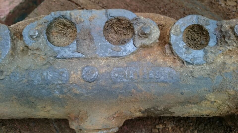
In the first photograph, there are what look like markings in cartouches on the manifold. I can't do anything with them, but if you played with contrast and size, they might be readable. Best, of course, would be to examine them on the object.
Good luck
Good luck
Join Date: Aug 2008
Location: Nottingham, U.K.
Posts: 53
Likes: 0
Received 0 Likes
on
0 Posts
Any other, legible markings on them?
Try asking in the "Historic" section of the Flypast Forum.
Key Publishing Ltd Aviation Forums
Good luck.
Don
Try asking in the "Historic" section of the Flypast Forum.
Key Publishing Ltd Aviation Forums
Good luck.
Don
Thought police antagonist
Join Date: Jul 2003
Location: Where I always have been...firmly in the real world
Posts: 1,372
Received 118 Likes
on
85 Posts
Purely a guess, but.
The first shot shows what appear to be locking plates.
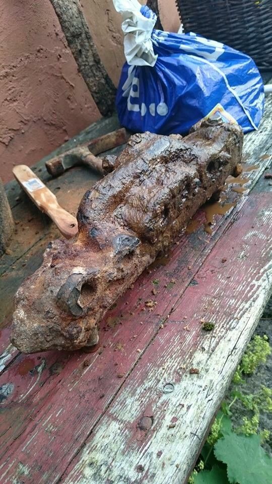
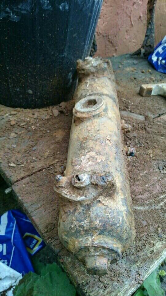
The last one, and with the end cap in particular, some sort of accumulator perhaps given the size of the component in comparison to the bucket.
The manifolds also suggest something like a shuttle valve or brake control valve.
The first shot shows what appear to be locking plates.
The last one, and with the end cap in particular, some sort of accumulator perhaps given the size of the component in comparison to the bucket.
The manifolds also suggest something like a shuttle valve or brake control valve.
Last edited by Krystal n chips; 19th Aug 2015 at 08:19.

Join Date: Jan 2008
Location: Frome - where we do as Fromans do.
Age: 68
Posts: 57
Likes: 0
Received 0 Likes
on
0 Posts
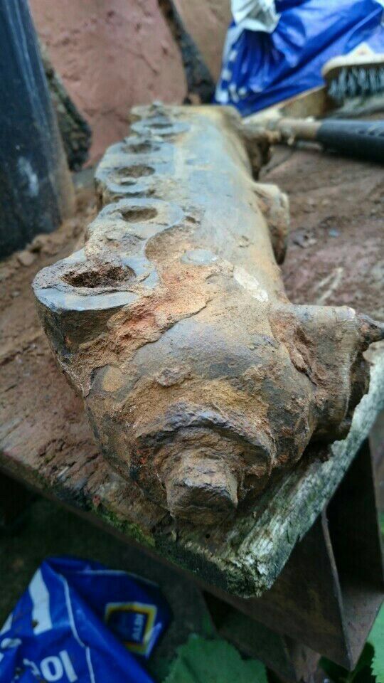
To my eyes, that is almost certainly a combined inlet and exhaust manifold for a four cylinder engine. The two centre and two end ports are the exhaust ports and the two remaining are inlet that would go to a 'Y' port created within the cylinder head. The carburettor would have been located to the left of the first picture attached to the ports number 2 and 5 and an exhaust pipe connected to the main body of the manifold either at the unseen end or, perhaps via the two connecting parts visible at either end of the manifold in the third picture - albeit that in this case, the gas flow would probably be somewhat restricted.
This arrangement of a manifold is absolutely typical of engines from the early days and there are probably still some engines being manufactured using the same design today.
Given that the object looks to be rather solid cast iron with no attempt at weight saving, it may well be more likely to come from a wheeled vehicle rather than one for flight...
Join Date: Oct 2007
Location: Norfolk U.K.
Age: 68
Posts: 448
Likes: 0
Received 0 Likes
on
0 Posts
Looks quite like a water-cooled boat manifold to me

Join Date: Oct 2007
Location: Norfolk U.K.
Age: 68
Posts: 448
Likes: 0
Received 0 Likes
on
0 Posts
Water heated, surely?
Looks quite like a water-cooled boat manifold to me.
