For those interested ... Here are some pics and narrative that attempt to record the further mods that have been carried out to WK518 and WG486 in the recent past. I would just caveat the following post by saying that the information has been drawn from various sources and interpreted with my best endeavours. I'm more than happy to receive corrections or additional information to help make the 'record' more complete

Image Credits (except the Avionics pic) : S. Elsworth BBMF Photographer.
External Fuselage Changes
I'm using WK518 as the example here ... I understand WG486 has a 'mirror' fit.
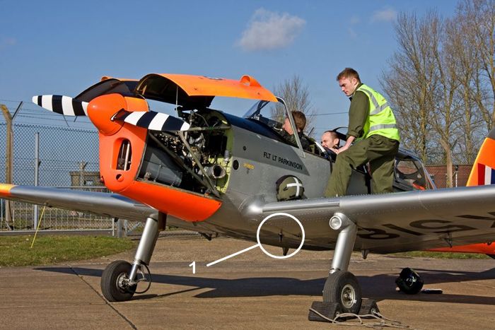
(1) The location of the external SSR/Transponder aerial.
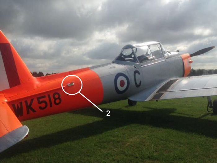
(2) I believe this is the location of the Starboard FLARM aerial. This aerial is replicated on the Port side of the rear fuselage in the same relative position.
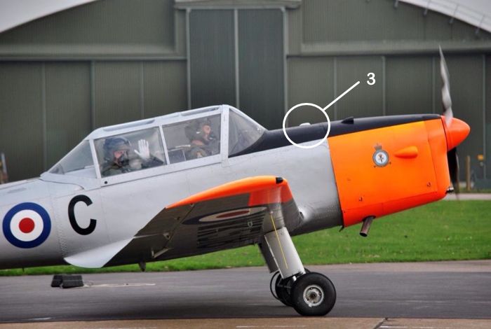
(3) I believe this is the location of the GPS Receiving aerial.
Internal Cockpit Changes
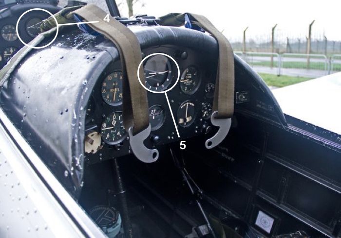
(4) Front Cockpit Artificial Horizon. I have included this pic mainly for it's curiosity value. If I remember correctly ... both Front and Rear Panels were equipped with the Mk1(e) Vacuum Driven AH ... which was a mod that introduced a 'Non-Toppling' AH to the UK Mil Chipmunk. However, it would appear that WK518, in this pic, has an earlier AH (possibly a Mk1(b)) fitted to the Rear Panel (5). The Front AH has a 'pivot' in the centre of the instrument glass supporting the 'gull wing' with the Horizon Bar 'broken'. The Rear AH doesn't have a 'pivot' and has a continuous Horizon Bar. If memory serves me correctly the fore-and-aft pivoting of the gyro prevented toppling during aerobatics ... But I'm sure someone with greater NavInst knowledge will elucidate further

It's quite possible that supplies of these rare vacuum Mk1(e) AH are such that priority might need to go to the BBMF Fighters ... just a thought
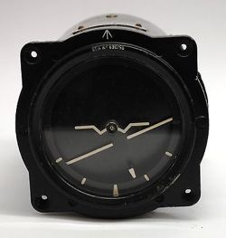
Image Credit : Unknown : Artificial Horizon Mk1(e)
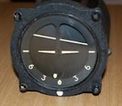
Image Credit : Unknown : Artificial Horizon Mk1(b)
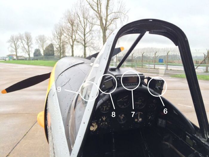
(6) I believe this is the location of the Mode S Transponder. Given the fit of 1950's Altimeters, I'm not certain how Height Encoding is achieved. It's possible that a separate Height Encoding unit is used or an interface with the GPS. Hopefully someone might know ?

Image Credit : Becker XPDR (Remote Head Close Up)
(7) This is the location of the combined Garmin Comms and GPS Nav. The model looks like the GNC250XL which provides 760 Chan VHF Comms (5 Watts). I'm not sure if remote operation is possible from the rear seat ... but I wouldn't have thought that was a priority given the current role of these aircraft. They appear to remain 'Single Box' VHF equipped (no UHF of secondary VHF) and still use the Starboard under wing 1/4 wave VHF aerial.
There is a facility to load a data 'brick' on the LH side of the Garmin to upload a pre-planned route ... but I don't know if BBMF use this functionality.
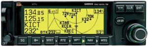
Image Credit : Garmin (Close Up)
(8) This is the location of the FLARM screen and panel.
The FLARM system transmits position, height and projected flight path and receives similar information from other FLARM equipped aircraft. The pilot is presented with a display showing all nearby aircraft and receives a warning in the event of a potential collision.

Image Credit : Butterfly PowerFLARM (Close Up)
(9) This is the location of the Accelerometer/G-Meter.
I'm sending our good friend
RNHF_PILOT a PM in the hope that we can update this thread with the two remain Chipmunks in RN Mil Service.
Best ...
Coff.