roulishollandais
Nice pictures!

But they are theoretical evaluations of the flow in a channel and the flow is subject to three (open channel) or four (closed rectangular channel) boundary layers. With fully developed boundary layers there is no real freestream conditions.
I would be surprised if the results shown resulted from anything more complex than application of a single initial condition. But we know that the output from strange attractors is extremely sensitive to initial conditions (butterfly wing flap to tornado). In real life the boundary layer will be subjected to an infinitely variable and random set of initial conditions as it passes over rivet heads, steps, gaps etc. So I suspect that the chaos in the boundary layer flow will be a lot more complicated than that shown in your photos.
]If we do consider freestream of course then there will always be some level of turbulence, but we must consider how the scale of the turbulence relates to the scale of the object passing through. [Scale here means the magnitude of a characteristic physical dimensional quantity such as wavelength]
Nobody would expect to see a neat set of streamlines surrounding an aircraft flying through a patch of turbulence, and the characteristic length used for load prediction is 2500 ft. I don�t know what the characteristic length would be for a hand launched model glider on a calm day, but I bet it isn�t as high as 762 meters!
If the air is calm (small scale turbulence) then although you would be correct in saying that there must be some turbulence the effect of this at distances greater than the boundary layer height away from the solid surface will be small and for all practical purposes we may assume streamline flow.
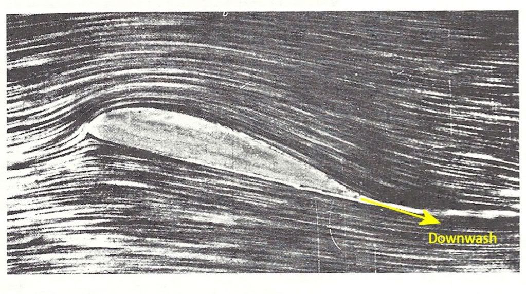
The picture below (taken by Prandtl) shows what I mean
@FlightPathOBN
Ah well, PJ2 told me I would get into difficulties with tip vortices ...
When the wing vortex (technically called the bound vortex) arrives at the wingtip the changed flow conditions cause it to change direction and continue rearwards as a trailing (aka wingtip) vortex. Since for any vortex the velocity increases and the static pressure drops as you move towards the core if the conditions are right any water vapour condenses out and we �see� the vortex as a contrail. These vortices are real! The only part of that statement that is correct is "these vortices are real" Let me take that bit by bit....
When the wing vortex (technically called the bound vortex) arrives at the wingtip the changed flow conditions cause it to change direction and continue rearwards as a trailing (aka wingtip) vortex.
To use someone else�s words (taken from Wikipedia, my emphasis)
Three-dimensional lift and the occurrence of wingtip vortices can be approached with the concept of
horseshoe vortex and described
accurately with the
Lanchester�Prandtl theory.
In this view, the trailing vortex is a continuation of the wing-bound vortex inherent to the lift generation
I stick with my statement
Since for any vortex the velocity increases and the static pressure drops as you move towards the core if the conditions are right any water vapour condenses out and we �see� the vortex as a contrail
Sorry, but you are just plain wrong when you say this isn�t true � again taking words from Wikpedia as I can�t be bothered to look up more erudite references
Depending on ambient atmospheric humidity as well as the geometry and wing loading of aircraft, water may condense or freeze in the core of the vortices, rendering them visible.
The core of a vortex in air is sometimes visible because of a plume of water vapor caused by
condensation in the low pressure and low temperature of the core; the spout of a tornado is a classic example
[quote]The illustrations that are provided with the entire post are oversimplified and misapplied to wake turbulence...Well I prefaced my explanation with :
With apologies to both those who think the following is dumbed down and those who think it too complicated, this is an attempt to put the math into plain words.
And I never once mentioned wake turbulence � I was attempting to explain the circulation theory of lift generation on the wing.
This is likely the result of a reliance on CFD models, and other nonsense that has prevailed for many years, but is now thankfully being addressed. These illustrations show a wing section in a wind tunnel, with simulated winds. Smoke or other methods are used to detect the airflow around the wing section, or even a wave tank with colored water.
Let me say that I am an old fashioned aerodynamicist � I have never in my life used or calculated using CFD. Similarly, the illustrations I used predated extensive use of CFD by many years � Shevell (1983), Gentry (1981) and even Prandtl (1908 I think). So I think your argument that the explanation results from over reliance on CFD is misplaced � and incidentally I don�t think you would find many modern aerodynamicists who would agree with you that CFD is �nonsense�!
Notice that the airflow in the section is not deflected? How is lift generated of airflow is not deflected?
Good spot! But the reason the airflow is not deflected is that this was a
one of a sequence of photographs (taken by Prandtl) and chosen by me to illustrate the
starting vortex formation. At that point in time the starting vortex had barely left the wing TE and the opposing wing circulation had not been generated. No circulation/no lift and no air deflection (downwash).
But a very short time later in the sequence the starting vortex has moved away, there is circulation around the wing and there is downwash, as in the picture above.
Rollup of the vortices occurs at the location of the wing where the laminar flow over the top of the wing disconnects from the top of the wing surface, NOT at the wingtips. (notice on your illustration that the condensation trail originates from the outward edge of the flap)
I think you must have a completely different conception of laminar flow to that held by most people working in the field. There is no laminar flow over pretty well the whole of the wing top surface (or over the whole aircraft for that matter. The boundary layers are turbulent as shown by roulishollandais photos above. I think what you mean is simple attached flow?
What has been oversimplified is the illustrations noted. There is no accounting for the weight and varied surfaces of the aircraft/wing, and in general, the overall issue that air can be compressed, while water cannot.
As I have said, I was not trying to do anything other than explain how lift is generated. Weight, control surfaces, compressibility are all extraneous factors with no relevance to a simple explanation of lift although they can obviously affect wake turbulence which I understand to be a preoccupation.
It is relatively easy to see the illustrations that have used CFD, such as those you have shown, but as we are finding out...cannot explain wake vortex creation.
As I said, I tried to keep it simple, but since you have brought it up, the explanation for the strong vortices off the flap tip is that the lift/unit span is given by rho*airspeed*Circulation. Over the part of the wing covered by flaps the lift/unit span is much greater than that on the unflapped bit. Since rho and airspeed are the same that means that the circulation is much bigger over the flapped part so that when the flap stops there is an abrupt change in circulation - and circulation is simply the strength of the vortex. Vorticity cannot just start or stop in midair and since the outer part of the wing cannot support it this high level of flap vorticity becomes another trailing vortex. Rather like a wing within a wing perhaps?
The 757 picture you posted is very interesting as it clearly shows the vortex �bursting� some way behind the wing. As AoA increases this bursting point gets closer and closer to the TE.