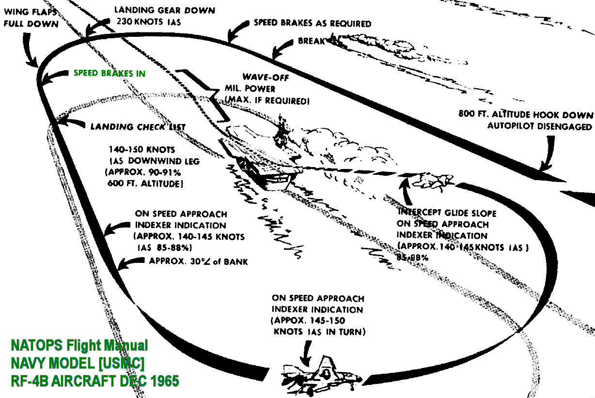
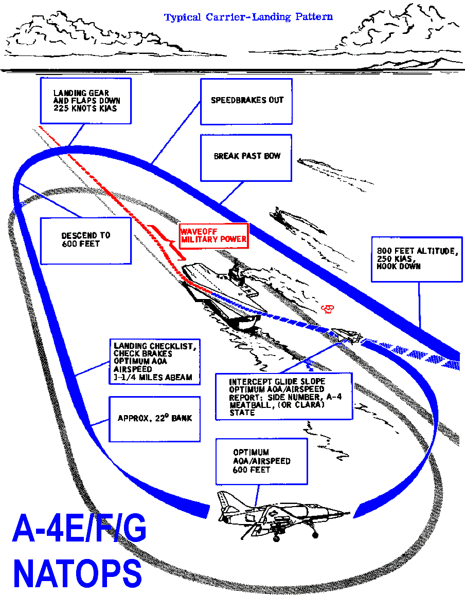
'Lordflasheart' some many years ago now when my work on the trashy virus filled PDFs (according to some on this forum) started I recalled that in 1970 initially our A4G / HMAS Melbourne circuits were at 400 feet with a level base turn. It was easy to pick up the
mirror just before the 90 degree mark (half way round the turn more or less) and to fly the meatball during the turn for a quick finals. Then as I recall we used the NATOPS carrier circuit height (level initial and level downwind though) of 600 feet. Generic A4G NATOPS day circuit was 800 feet initial descending downwind to 600 feet as per the RF-4B diagram. The 1970 circuit was more like that of the Sea Venom when a tight circuit was SOP, while the change to 'NATOPSlike' circuit was from 1971 or thereabouts. I preferred the low circuit with the level base turn, the higher descending base turn was just sloppy IMHO. There was a transition from the 'old bolds' from the Sea Venom days to the new LSO enabled A4G NATOPS and eventually LSOs and NATOPS ruled.

Reading the NATOPS (and other source) methods for modern day USN aircraft was a surprise (as mentioned by others) to see that the carrier day circuit is so heavily reliant on instruments (I guess much more accurate today) especially the first half of the descending base turn. The quick visual 400 feet early A4G carrier circuit was quick and efficient and a lot of fun.
Click the pics:


