you can say that thrust is created by the pressure difference across the nozzle
How Rolls Royce explains thrust generation, the nozzle is only part of the story.
Although the principles of jet propulsion will be familiar to the reader, the distribution of the thrust forces within the engine may appear somewhat obscure- These forces are in effect gas loads resulting from the pressure and momentum changes of the gas stream reacting on the engine structure and on the rotating components. They are in some locations forward propelling forces and in others opposing or rearward forces. The amount that the sum of the forward forces exceeds the sum of the rearward forces is normally known as the rated thrust of the engine.
The diagram is of a typical singlespool axial flow turbo-jet engine and illustrates where the main forward and rearward forces act. The majority of the thrust in the example is provided by the combustion chamber (34,182 lbs) and secondly by the compressor (19,049 lbs).
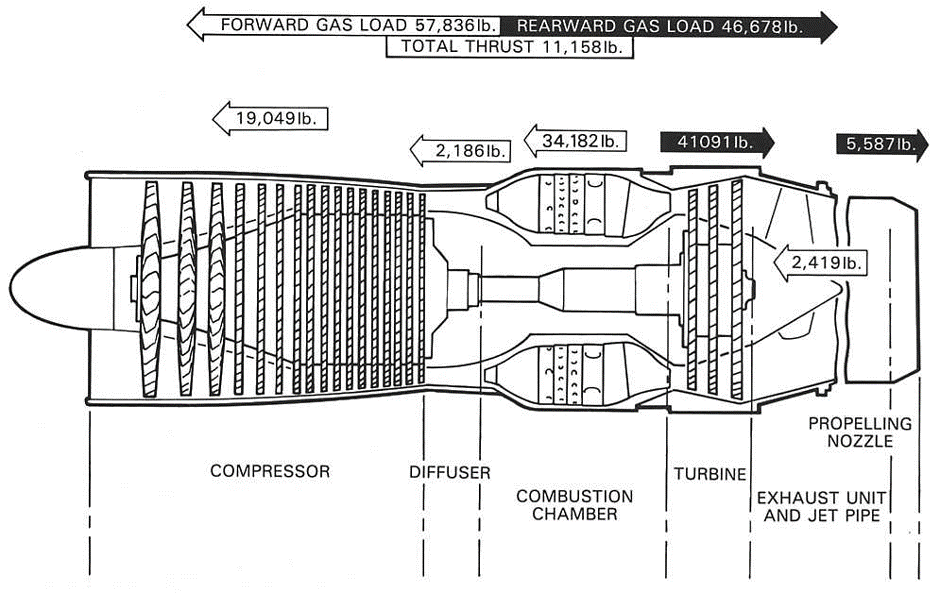
At the start of the cycle, air is induced into the engine and is compressed. The rearward accelerations through the compressor stages and the resultant pressure rise produces a large reactive force in a forward direction. On the next stage of its journey the air passes through the diffuser where it exerts a small reactive force, also in a forward direction,From the diffuser the air passes into the combustion chambers where it is heated, and in the consequent expansion and acceleration of the gas large forward forces are exerted on the chamber walls.
When the expanding gases leave the combustion chambers and flow through the nozzle guide vanes they are accelerated and deflected on to the blades of the turbine. Due to the acceleration and deflection, together with the subsequent straightening of the gas flow as it enters the jet pipe, considerable �drag� results; thus the vanes and blades are subjected to large rearward forces, the magnitude of which may be seen on the diagram. As the gas flow passes through the exhaust system, small forward forces may act on the inner cone or bullet, but generally only rearward forces are produced and these are due to the �drag� of the gas flow at the propelling nozzle.
It will be seen that during the passage of the air through the engine, changes in its velocity and pressure occur. For instance, where a conversion from velocity (kinetic) energy to pressure energy is required the passages are divergent in shape, similar to that used in the compressor diffuser. Conversely, where it is required to convert the energy stored in the combustion gases to velocity, a convergent passage or nozzle, similar to that used in the turbine, is employed. Where the conversion is to velocity energy, �drag� loads or rearward forces are produced; where the conversion is to pressure energy, forward forces are produced.