Originally Posted by
Smythe
FDR...verbose as you are , it is not correct on many fronts..
That is what I stated, stick feel is a result of aerodynamics, not the other way around...
You misquoted what I stated. Surfaces do go transonic, I did not mention only low speed, but high AOA...Boeing does mention low speed stall, AND high AoA AND high G ....not inclusive. Many surfaces go transonic on the wing, fuselage and cowlings...
Boeing DOES state that in testing, they found airflow over the wing went transonic, and tried to alleviate this issue with vortex tabs and changing the wing design...Boeing own words, not mine.
No laminar flow over the wing??? Really...explain this video:
https://www.youtube.com/watch?v=HekbC6Pl4_Y
Again, as verbose as that is, how does it relate to the MAX stalling at relatively low AoA comparatively? On low speed final, it pushes the nose down 2.5 degrees to avoid stall...what AoA are you at on final?
.
Of course, that is why they still have vortex tabs running down the wing....but you say this cures issues of separation, but deny laminar flow over the wing?
But we do appear to agree that he stick feel is a result, correct?
We are over 105 days on the grounding, and the FAA found another issue. Perhaps unstable is a bit harsh, but certainly, in many conditions , it is not predictable....
What if MCAS is far more reaching than Boeing has stated? It certainly appears to be. Perhaps the half FBW design has inherent flaws that were either unintended or incorrectly implemented in the software?
Again, over 100 days says that MCAS may be a lot more active than anticipated.
I completely agree the pilots deserve more. I also think that there are many unintended consequences that can line up in the software...and MCAS is far more active than thought...again, over 100 days, and still finding issues....
How is the low speed stall issue, not a stall issue? Stick pressure was not mentioned, simply low speed stall. MCAS was designed to push the nose down 2.5 degrees to prevent stall. Where is the interpretation here? 0.6 pitch up on DEP, okay, some lift and stick feel, but jeez, 2.5 on final? (of course, as we all know, its all 2.5 now) What about high G? Where the heck does MCAS come into play in this scenario?
I'm off on a test flight, however will leave the following reading list for you Smythe, and I will respond later... Being verbose, possibly, however, your posts cover a lot of scope and therefore the responses are necessarily expansive.
Suggested Reading:
Start with Ira & Albert... Theory of Wing Sections, an oldie but a goodie.
then:
Lin, J. C. (NASA). (2002). Review of research on low-profile vortex generators to control boundary-layer separation.
Progress in Aerospace Sciences,
38(4–5), 389–420.
https://doi.org/10.1016/S0376-0421(02)00010-6
Lin John C. (1999). Control of Turbulent Boundary-Layer Separation using Micro-Vortx Generators. In
30th AIAA Fluid Dynamics Conference. Norfolk, VA: AIAA.
Crawford, B. K., Jr, G. T. D., West, D. E., & Saric, W. S. (2014). Quantitative Boundary - Layer Transition Measurements Using IR Thermography.
AIAA SciTech,
2013(July), 233–239.
https://doi.org/10.2514/6.2014-1411
Schobeiri, M. T., Öztürk, B., & Ashpis, D. E. (2007). Effect of Reynolds Number and Periodic Unsteady Wake Flow Condition on Boundary Layer Development, Separation, and Intermittency Behavior Along the Suction Surface of a Low Pressure Turbine Blade.
Journal of Turbomachinery,
129(1), 92.
https://doi.org/10.1115/1.2219762
Sapuppo, J.; Archer, R. D. (1982). Fully laminar flow airfoil sections.
Journal of Aircraft,
19(5), 406–409.
https://doi.org/10.2514/3.44763
Cohen, G. (2007).
Control of shock-induced boundary layer separation at supersonic speeds. Queen Mary University of London. Retrieved from
https://qmro.qmul.ac.uk/jspui/handle/123456789/1724
Cowley, S. J. (n.d.). LAMINAR BOUNDARY-LAYER THEORY : A 20TH CENTURY PARADOX ?, (1981), 1–23.
Xingyu, M., Geisler, R., Agocs, J., & Schr"{o}der, A. (2014). Time-resolved tomographic PIV investigation of turbulent flow control by vortex generators on a backward-facing step.
17th International Symposium on Applications of Laser Techniques to Fluid Mechanics, Lisbon, 2014
Heap, H. (n.d.). A REVIEW OF CURRENT LEADING EDGE DEVICE TECHNOLOGY AND OF OPTIONS FOR, 1–13.
Knob, M. (2009). Dynamics of a boundary layer separation.
Engineering MECHANICS,
16(1), 29–38.
Schanz, D., Schr�der, A., Heine, B., & Dierksheide, U. (2012). Flow structure identification in a high-resolution tomographic PIV data set of the flow behind a backward facing step. In
16th Int Symp on Applications of Laser Techniques to Fluid Mechanics Lisbon, Portugal, 09-12 July, 2012 (pp. 9–12).
Ashpis, D. E. (2005). on Boundary Layer Development , Separation , and Re-attachment along the Suction Surface of a Low Pressure Turbine Blade. In
GT2005 ASME Turbo Expo 2005:Power for Land, Sea and Air.
Anyiwo, J. C. (1973). A force field theory. Part I - Laminar flow instability.
AIAA Journal,
11(1), 43–49.
https://doi.org/10.2514/3.6668
Reed, H. L. (2011).
Laminar-to-Turbulent Stability and Transition. Flight Research Laboratory, Texas A&M University
Watmuff, J. H. (1995).
Boundary Layer Transition Studies MCAT Institute Final Report. NASA CR-NCC2-698-95-12
Muraca, R. J. (1978). Laminar flow control overview. In
47th AIAA Aerospace Sciences Meeting Including The New Horizons Forum and Aerospace Exposition 5 - 8 January 2009, Orlando, Florida (pp. 1–13). Orlando: AIAA 2009-381.
Jobe, C. E., Kulfan, R. M., & Vachal, J. D. (1979). APPLICATION OF LAMINAR FLOW CONTROL TO LARGE SUBSONIC MILITARY TRANSPORT AIRPLANES.
Journal of Aircraft,
16(3), 78–95.
Joslin, D. (1998).
Overview of Laminar Flow Control.
NASA/TP-1998-208705. Hampton VA.
Hefner, J. N., & Sabo, F. E. (Eds.). (1987). Research in Natural Laminar Flow and Laminar-Flow Control. In
NLF Symposium held at Langley Research Center, Hampton Virginia, March 16-19, 1987. Hampton VA: NASA.
Park, G. I., Wallace, J. M., Wu, X., & Moin, P. (2012). Boundary layer turbulence in transitional and developed states.
Physics of Fluids,
24(3), 77–86.
https://doi.org/10.1063/1.3693146
Thomas, A., Saric, W., & Braslow, A. (1985).
Aircraft Drag Prediction and Reduction. Retrieved from
http://oai.dtic.mil/oai/oai?verb=getRecord&metadataPrefix=html&identifier=ADA160718
Lange, R. H. (1984). Design integration of laminar flow control for transport aircraft.
Journal of Aircraft,
21(8), 612–618.
After a while you will get a sense of the the sensitvity of an laminar flow to transition to turbulent. A simple analysis is done online, where a shape factor, H32, d3/d2
is less than the following value:
above that value, transition is expected to occur.
Your video shows a 738 or similar wing in transonic flight, the aircraft is at about M0.785 to M0.795, and has an aoa of around 2.3-2.5. In front of the shock, the flow is turbulent, behind the shock it has a layer of separated flow extending rearwards from the shock boundary layer foot. Not sure hat your point is. Any laminar flow on that wing has stopped on the left hand side, at, or before the flow got to the aft facing step of the slat on the wing. Oddly enough, for the last 5 years of testing the B737 in transonic drag reduction related to this very matter, we have seen various configurations that gave considerable drag reduction. Conventionally, a slat is expected to add 1% to total drag, however that neglects the step effect.
the following image is post flight from NASA on a LR31 test using sublimating chemicals to undertake visualisation of transition. Quoniam res ipsa loquitur. hot wire anemometry etc has often been used to detect transition, however we have found that such methods alter the experiment, as they introduce boundary trips to the experiment.
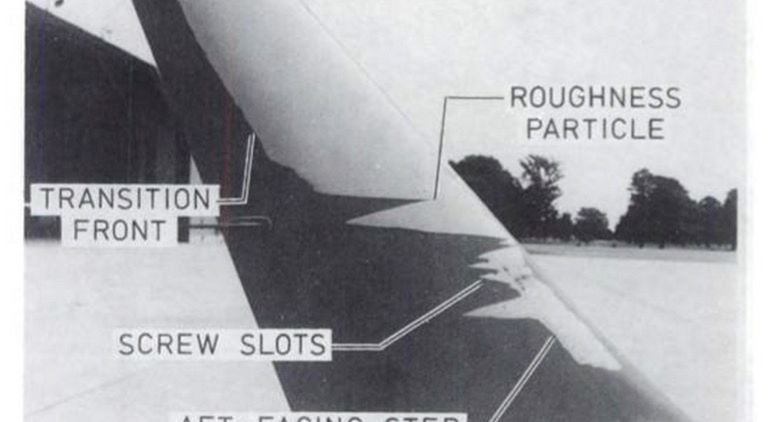
Is the photo succinct enough?
P.S.
the shockwave on the video is forward of that modelled by the manufacturer in their CFD. Just one of those things of modelling a monolithic meshed section that is simplified in order to attain rational CPU hours. It also exhibits instability, which arises from the shedding of the flow structure immediately behind the slat TE, and that happens about 10x more frequently than the vibration frequency of the shock as imaged. The shock motion does not correlate to engine vibration, or to the acoustic impingement on the bottom of the wing, which was an area of some research in the past by NASA and OEM's. BTW, the shock is observed at the point where the flow decelerates to subsonic, everything to the left of that with the exception of the separation area immediately behind the slat step is sonic, with the exception of the Kutta point which has zero velocity.
Most if not all 3D semi span models do not incorporate the slat as built, which gives a step in a critical part of the airfoil, The neatest example was the EMB170 wing CFD which shows a SC02 type pressure pattern, with a shock location around 0.8c, yet the same conditions in flight video the shock at 0.35-0.4c. The CFD had no slat... The difference in section drag count in detail testing is on the order of 25%-28% optimistic to that with a slat, a solution that tied up my own supercomputer for months to get, and took out the resources of the software supplier to run for a substantial time and cost.
The B737 wing is transonic in cruise, unless at very light weights, low mach, and or low altitude, as most transport aircraft are, by memory, above around M0.745 you will achieve Mcrit on the BAC section at average weights for altitude. Increase AOA, and the speed reduces to achieve Mcrit... and v.v.
Details matter.