


Drag of a seized jet engine compared to windmilling

[QUOTE=tdracer;10604835]I've been thinking about this, and I think the answer is that when a fan is windmilling, the fan blade airfoils are basically working as intended - the angle of attack of the blades is within the range that the flow won't separate and the airfoil stall. Hence the pressure loss through a windmilling fan is small. If the fan is locked, the incoming air is hitting the fan blade at a very high angle of attack - beyond the stall angle - so the fan blades are effectively stalled with the associated large pressure drop (i.e. drag). So there is a greater pressure loss through a locked fan than a windmilling fan, and that equates to more aerodynamic drag. I'm unaware of any engines that drive accessories off of the LP rotor so that doesn't come into play (the core would be a different question). {/quote]
Not quite. In both cases, locked and windmill, the angle of attack is on the convex side rendering the blade stalled.The differences in drag are due to what is going on in the compressor which is working to pressurize the burner sufficient for re-start, if you're going fast enough.Kinda like a ramjet
Not quite. In both cases, locked and windmill, the angle of attack is on the convex side rendering the blade stalled.The differences in drag are due to what is going on in the compressor which is working to pressurize the burner sufficient for re-start, if you're going fast enough.Kinda like a ramjet

Join Date: Oct 1999
Location: Up there
Posts: 202
Likes: 0
Received 0 Likes
on
0 Posts
A fan producing thrust is obviously providing a forward lifting force towards the front of the engine (+ thrust) while a fan being spun by the relative airflow is now providing a fan force towards the rear of the engine due to a lift force on the rear side of each blade (-thrust)
Windmill drag is obviously significant enough that aircraft now use thrust on descent to reduce drag. While I remember the A330 having it from what I imagine was service entry, you�d descend with an EPR of 1.0 or so, the 747 only got thrust on descent with the NGFMC and the introduction of the 747-8 ie circa 45 years late.
So we�re back to the beginning is the interference drag reduced more or less than the negative thrust component caused by a windmilling engine?
I guess you could plot windmill N1 / EPR vs airspeed and see if it�s a direct correlation or find a aerodynamicist.
I�m going with windmilling has more total drag or penalty than a locked fan.
Logs added to fire.....
Join Date: Nov 2005
Location: Zulu Time Zone
Posts: 730
Likes: 0
Received 0 Likes
on
0 Posts
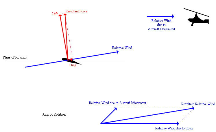
If you measured the rate of descent of a chopper with a fixed rotor, you'd find it initially would descend slower than one performing an auto-rotation maneuver. With a fixed rotor and a vertical descent, the air will be hitting the rotor blade nearly perpendicular - making the rotor basically just a big flat plate to the air (the drag coefficient of a flat plate perpendicular to the airflow is nearly 1.0 - which is roughly the same as a parachute. In short fixed rotor blades become a huge drag source during a vertical descent. In contrast, the blade pitch during an auto-rotation is controlled to specifically prevent it from stalling - using the resultant rotational lift component to accelerate the rotors to a high speed so that the kinetic energy an be used to create lift and slow the descent in the last second before impact. There is some induced drag associated with creating the lift that provides the rotational acceleration, but it's much less than the drag created by a fully stalled rotor blade.
Last edited by oggers; 28th Oct 2019 at 10:34.
Join Date: Mar 2014
Location: Way north
Age: 47
Posts: 497
Likes: 0
Received 0 Likes
on
0 Posts
Seen from an energy point of view...
To get the engine spinning, you need energy.... and that energy comes from "stored energy" (in case of a dead engine), that stored energy will be the altitude below the aircraft, or the fuel in the tanks etc.
So no matter how you twist and turn it, if you have an engine windmilling, you're using energy to get that engine windmilling, that requires extra thrust on the other engine(s), hence extra fuel consumption.
I have to think a little more about the drag thing though, but I'm confident oggers has it nailed here.
Does this help?

Join Date: Apr 1998
Location: Mesopotamos
Posts: 5
Likes: 0
Received 0 Likes
on
0 Posts
I read recently a simple explanation, the energy that the aircraft is using to push itself through the air is being reduced as some of that energy is being used to spin the windmilling blades.
A lot would also depend on the engine size, design, location, airspeed, etc, an interesting question nonetheless.
Join Date: Mar 2014
Location: Way north
Age: 47
Posts: 497
Likes: 0
Received 0 Likes
on
0 Posts
So what you are saying, since the relative wind in relation to a windmilling engine, is that the AoA is actually "inverse", and the lift generated by the windmilling engine, is actually opposite direction of the lift generated by a normal operating engine? So the lift goes towards the rear, hence increasing the drag??
Thinking a bit about it, I can buy that, looking at the example of the gyro copter.
Thinking a bit about it, I can buy that, looking at the example of the gyro copter.
In a CM56 jet engine if the core of the engine seizes completely for whatever reason, will the N1 fan still rotate freely?
In the 737-300 simulator, actuation of "turbine seizure" selector on the instructor panel causes significant noise and heavy vibration and eventually the N2 indicates zero but the N1 still indicates rotation; albeit around 10 N1 only. Does turbine seizure mean engine core seizure? Or are they both different parts of the engine?
In the 737-300 simulator, actuation of "turbine seizure" selector on the instructor panel causes significant noise and heavy vibration and eventually the N2 indicates zero but the N1 still indicates rotation; albeit around 10 N1 only. Does turbine seizure mean engine core seizure? Or are they both different parts of the engine?
Join Date: Jan 2013
Location: Seattle Area
Posts: 263
Likes: 0
Received 0 Likes
on
0 Posts
It sounds like imprecise language is used in those simulator controls. The N1 (fan) shaft and the N2 (core) shaft both have turbine stages at the back end. The rotation of the two shafts is not mechanically connected. The core being seized or simply not turning due to accessory drag at low airspeed will not directly mechanically affect rotation of the fan shaft. It sounds like the "turbine seizure" selector you describe simulates a stopped core shaft and tries to simulate some sort of N1 system mechanical failure. It's not clear what actual mechanical failure the designers were trying to simulate. The heavy airframe vibration they simulate with N2 at zero obviously is intended to represent damage to the N1 system, like out of balance or bearing failure. Failure of the N2 turbine that releases parts in the gas path often will cause heavy damage to the downstream N1 stages.
Join Date: Mar 2007
Location: Another Planet.
Posts: 559
Likes: 0
Received 0 Likes
on
0 Posts
Engine fire as a result of IFSD??
Let alone continuing on 3 of 4 assuming adequate terrain clearance when the next one fails?
I�ve been P2 on 6 3-engined ferrys all of which had the fan etc tethered by proper engineering kit, especially the one with the remains of a borescope in it!
And yes, there was a 747 transiting through Europe with the front end tethered by a collection of leather belts and other Heath Robinson improvised devices. It was impounded by the relevant xAA until a more airworthy solution was found and the subsequent dispatch proven as legal and compliant.
Join Date: Sep 2016
Location: USA
Posts: 803
Likes: 0
Received 0 Likes
on
0 Posts
Well, an airbrake has interaction with the airstream - it slows the aircraft down. So a locked fan will extract energy from the airflow because it is, in effect, a large circular airbrake. But I don�t know how to calculate if that energy would be greater than if the fan was rotating.
I agree that energy transfer is one way of telling the whole story. I guess my real point was that energy transfer into the engine isn't the whole story -- you'd have to consider energy transfer into the atmosphere through vortices and such as well. That makes the analogy to a clutch on a car running down the hill less useful.
Vessbot, the helicopter analogy is invalid because of the way the blade pitch is varied during an auto-rotation. If you measured the rate of descent of a chopper with a fixed rotor, you'd find it initially would descend slower than one performing an auto-rotation maneuver. With a fixed rotor and a vertical descent, the air will be hitting the rotor blade nearly perpendicular - making the rotor basically just a big flat plate to the air (the drag coefficient of a flat plate perpendicular to the airflow is nearly 1.0 - which is roughly the same as a parachute. In short fixed rotor blades become a huge drag source during a vertical descent. In contrast, the blade pitch during an auto-rotation is controlled to specifically prevent it from stalling - using the resultant rotational lift component to accelerate the rotors to a high speed so that the kinetic energy an be used to create lift and slow the descent in the last second before impact. There is some induced drag associated with creating the lift that provides the rotational acceleration, but it's much less than the drag created by a fully stalled rotor blade.
In reality they both have the same drag coefficient, but the latter will have much more weight, which will oppose drag and accelerate downward faster, reaching a speed (terminal velocity) where the much higher weight is balanced by equally much higher drag.
I still maintain that an autorotating helicopter is a good analogy.
Not quite. In both cases, locked and windmill, the angle of attack is on the convex side rendering the blade stalled.The differences in drag are due to what is going on in the compressor which is working to pressurize the burner sufficient for re-start, if you're going fast enough.Kinda like a ramjet
Last edited by Vessbot; 31st Oct 2019 at 04:57.
Join Date: Jan 2013
Location: Seattle Area
Posts: 263
Likes: 0
Received 0 Likes
on
0 Posts
I was able to dig out the drag analysis from several years ago supporting a three engine ferry performance data approval which showed that, for a nacelle mounted high bypass engine, the nacelle with a non-rotating fan has appreciably higher drag than that same nacelle with a windmilling engine.
Thread Starter
I was able to dig out the drag analysis from several years ago supporting a three engine ferry performance data approval which showed that, for a nacelle mounted high bypass engine, the nacelle with a non-rotating fan has appreciably higher drag than that same nacelle with a windmilling engine.

Join Date: Jan 2013
Location: Seattle Area
Posts: 263
Likes: 0
Received 0 Likes
on
0 Posts
Unfortunately, because I don't personally own the data, I have to be careful not to release information that might be considered proprietary.
However (and this is now just me talking about the physics as I understand it), I hope most of us can agree that a fully plugged nacelle (entire fan duct and core path blocked) would have more drag than a nacelle with a windmilling fan due to the effects of 100% spillage. The nacelle with a stopped fan behaves a lot like a nacelle with a fully plugged fan because the flow through the fan duct is greatly reduced versus a windmilling engine. The stream of air that actually flows through the nacelle is greatly reduced in diameter when the fan is stopped, unlike when a propeller is stopped, due to the high solidity of the fan and the exit guide vanes relative to the flow direction and the total effect of the tortuous path the air has to follow to get around the fan blades and the exit guide vanes (which are shaped and angled all wrong for this flow case). This "spilled" air, which has to get out of the way of the nacelle rather than pass through it, causes an appreciable amount of what I believe is referred to as interference drag, but I am not an aerodynamics engineer so that may be the wrong term.
However (and this is now just me talking about the physics as I understand it), I hope most of us can agree that a fully plugged nacelle (entire fan duct and core path blocked) would have more drag than a nacelle with a windmilling fan due to the effects of 100% spillage. The nacelle with a stopped fan behaves a lot like a nacelle with a fully plugged fan because the flow through the fan duct is greatly reduced versus a windmilling engine. The stream of air that actually flows through the nacelle is greatly reduced in diameter when the fan is stopped, unlike when a propeller is stopped, due to the high solidity of the fan and the exit guide vanes relative to the flow direction and the total effect of the tortuous path the air has to follow to get around the fan blades and the exit guide vanes (which are shaped and angled all wrong for this flow case). This "spilled" air, which has to get out of the way of the nacelle rather than pass through it, causes an appreciable amount of what I believe is referred to as interference drag, but I am not an aerodynamics engineer so that may be the wrong term.
its�5perworddammit
Join Date: Nov 2003
Location: the foxhole
Posts: 148
Likes: 0
Received 0 Likes
on
0 Posts
In the B-36, the jet engines are only used for the high speed dash over the target area. During cruise on piston power, nacelle doors cover the unused jet intakes. This design seems to run counter to the assumption that a blocked intake is draggier than windmilling engines.

Join Date: Jan 2013
Location: Seattle Area
Posts: 263
Likes: 0
Received 0 Likes
on
0 Posts
That shape is very different from the shape of an 8 foot diameter high bypass engine with a blockage 4 feet back in the inlet. I know nothing about that airplane except for admiring it's extremely complex cockpit in a panoramic viewer you can find on the internet. Try to find the jet engine controls if you don't already know where they are!
Last edited by Dave Therhino; 1st Nov 2019 at 03:05. Reason: deleted some incorrect speculation about reason for B36 engine louvers
Join Date: Sep 2016
Location: USA
Posts: 803
Likes: 0
Received 0 Likes
on
0 Posts
In the B-36, the jet engines are only used for the high speed dash over the target area. During cruise on piston power, nacelle doors cover the unused jet intakes. This design seems to run counter to the assumption that a blocked intake is draggier than windmilling engines.
1. Blocked/faired intake
2. Open intake with windmilling engine
3. Open intake with seized engine
And I've listed them in order of what I now think is least to most drag. (At the beginning of the thread I thought 2 and 3 were reverwed, until the few guys referenced the ETOPS data)
Join Date: Jan 2013
Location: Seattle Area
Posts: 263
Likes: 0
Received 0 Likes
on
0 Posts
Your item 1 is really two configurations that I suspect are the lowest and highest drag configurations, fully faired inlet being lowest drag, and nacelle with inlet fully blocked at the fan face being highest. The fully faired inlet is a theoretical case.
Last edited by Dave Therhino; 1st Nov 2019 at 03:28.
its�5perworddammit
Join Date: Nov 2003
Location: the foxhole
Posts: 148
Likes: 0
Received 0 Likes
on
0 Posts
Further research on the topic of spillage drag has led me to the text Gas Turbine Performance (P.Walsh/P.Fletcher) where it mentions spillage drag can range from 10 - 20 percent of internal drag in a pure turbojet, to appoximately equal to internal drag at a bypass ratio of 5:1. This does corrolate with the disconnect between the data from the old NACA reports using straight jets against what is being put forward here.
Its a good day when one sets off to prove someone wrong only to demise by his own sword!
The text references data from ESDU 81009, 84004 and 84005 - if anyone has access and could summarize it would be greatly apperciated.
Its a good day when one sets off to prove someone wrong only to demise by his own sword!
The text references data from ESDU 81009, 84004 and 84005 - if anyone has access and could summarize it would be greatly apperciated.
Last edited by mrfox; 1st Nov 2019 at 06:32. Reason: addd ESDU reference
Join Date: Sep 2002
Location: La Belle Province
Posts: 2,179
Likes: 0
Received 0 Likes
on
0 Posts
Higher drag with a seized engine.
All discussion of how the windmilling fan is extracting energy and thus must be creating more drag ignores the fact that a seized engine is essentially a giant blunt body with all kinds of intake spillage going on. That effect is way more than the windmilling. (All the windmilling needs to do is overcome the bearing drag once the engine is stabilized, which is not that big)
Am aware of an incident where significant engine damage caused one of a twin to seize. Max attainable altitude dropped from the theoretical ~25kft for a normal OEI case to below 15kft.