


Acceleration check procedure for liners

Only half a speed-brake
If the thrust is set for a desired (2.4 OEI) climb performance, depending on the mass of the aircraft, there would be a certain Thrust/Mass ratio. Not constant but as a function of flaps and the density altitude it should be pretty coherent. Per Sir Isaac's F=-a*m, by its mathematical definition, thrust to mass ratio IS the acceleration.
So where's the problem?
Obstacles requiring a higher than 2.4 ratio? I do not think so, with two running you'd clear them anyway.
But about the gradient: it is actually achieved by Lift /Mass, contrary to the suggestion I made above. The lift does evolve from the (square of) speed, but the required speed needs only to be achieved within the constraints of TODA/ASDA, so the acceleration required varies greatly. (lederhosen's post #12).
I still think the idea is good. Understanding the reasons why all the clever and experienced minds of yesteryear had not brought forward a solution already is part of the approach on how to crack the nut.
As a recap of the previous debates, the wide range of valid accelerations is part of the problem

Join Date: Jun 2007
Location: Wanderlust
Posts: 3,404
Likes: 0
Received 0 Likes
on
0 Posts
I think there is enough to monitor during take-off and no need to add anymore �made-up� acceleration check. Anyway, what happens when rvr 125m?
If both pilots check the the performance data and the numbers are cross checked when inserted into whatever electronic box the aircraft has, then good to go. Gross error check is also useful too.
If both pilots check the the performance data and the numbers are cross checked when inserted into whatever electronic box the aircraft has, then good to go. Gross error check is also useful too.
Only half a speed-brake
S7 at Domodedovo
MK Airlines at Halifax
EK at Melbourne
QR on the West Coast
BA out of the Carribean
and many many more. It may still be a very rare occurrence given the sheer departure numbers worldwide, but the severity is absolute. In a sense we are lucky the bright people had not been asked to provide a tool as of yet, since the outcome of the above was merciful on the travelling public.
Not that sure "ain't broke" is a valid evaluation. EGPWS and PWS, as well as the much-beloved FBW with protections, were all created above the contemporary burning needs.
I�ve thought for quite a while that a TOPM wouldn�t be such a hard device to implement. You know where the aeroplane is, how much runway is available, what the flap setting is, aircraft mass, temperature and wind component. It could produce a caution/warning after thrust has stabilised only if there was an apparent gross error, i.e. something that was way outside normal operation. Yes, there would have to be some intelligent filtering/processing of the data but it would also function to alert that some other parameters were incorrect.

I agree with FullWings that an electronic solution is certainly possible. But given airlines unwillingness to pay for stuff that might have prevented accidents (as suggested by Boeing now including things that were options previously in the 737 Max) it would probably only work if it was mandatory. Light aircraft rules of thumb (speed at halfway point for example) are great with full thrust takeoffs and familiar airfields. On the Airbus/Boeing aircraft I flew I don't think you can eyeball it and the incidents I heard about were mainly flap setting issues e.g. people setting flaps 1 with flaps 5 speeds. With experience you should spot on medium jets if something is strange about the V speeds, but much harder to spot acceleration problems on unfamiliar runways with varying met conditions.
Join Date: Sep 2016
Location: USA
Posts: 803
Likes: 0
Received 0 Likes
on
0 Posts
Climb gradient is a function of excess thrust, nothing to do with lift. (Some are surprised to learn that the steeper you climb, the less lift is actually required or produced by the wing.)
If the thrust is set for a desired (2.4 OEI) climb performance, depending on the mass of the aircraft, there would be a certain Thrust/Mass ratio. Not constant but as a function of flaps and the density altitude it should be pretty coherent. Per Sir Isaac's F=-a*m, by its mathematical definition, thrust to mass ratio IS the acceleration.
So where's the problem?
Obstacles requiring a higher than 2.4 ratio? I do not think so, with two running you'd clear them anyway.
But about the gradient: it is actually achieved by Lift /Mass, contrary to the suggestion I made above. The lift does evolve from the (square of) speed, but the required speed needs only to be achieved within the constraints of TODA/ASDA, so the acceleration required varies greatly. (lederhosen's post #12).
I still think the idea is good. Understanding the reasons why all the clever and experienced minds of yesteryear had not brought forward a solution already is part of the approach on how to crack the nut.
As a recap of the previous debates, the wide range of valid accelerations is part of the problem
So where's the problem?
Obstacles requiring a higher than 2.4 ratio? I do not think so, with two running you'd clear them anyway.
But about the gradient: it is actually achieved by Lift /Mass, contrary to the suggestion I made above. The lift does evolve from the (square of) speed, but the required speed needs only to be achieved within the constraints of TODA/ASDA, so the acceleration required varies greatly. (lederhosen's post #12).
I still think the idea is good. Understanding the reasons why all the clever and experienced minds of yesteryear had not brought forward a solution already is part of the approach on how to crack the nut.
As a recap of the previous debates, the wide range of valid accelerations is part of the problem
Only half a speed-brake
@vessbot
Perhaps I ventured too far. Hope the other message remains standing: for a given V2, there would be different acceleration schedules depending on runway length. Longer tarmac, less thrust, valid slower acceleration, satisfactory V2+10 at screen height by the end of CWY anyway.
Would you check your statement applies well in the second segment case, for climb angle of 1.4 deg with flaps out and perhaps 11 deg pitch?
The AFM data confirms that for the same thrust the climb gradient is better if IAS is increased, the so-called "improved climb V2 schedule". Without thinking too much about it, I was building on the classical vector cross with L in the upward sense opposing the W, and L = c(l) * area * 1/2 * density * v^2. It has got to work somehow, nay?
OTOH that thing I uttered above about obstacles is rubbish. Higher required gradient, more thrust needed and usually lower speeds. Which underlines your point.
Where have all my marbles are gone? (M. Dittrich tune)
That, for sure, is a physical necessity. I did not put the effort in to read your message properly before posting, apologies.
Perhaps I ventured too far. Hope the other message remains standing: for a given V2, there would be different acceleration schedules depending on runway length. Longer tarmac, less thrust, valid slower acceleration, satisfactory V2+10 at screen height by the end of CWY anyway.
Would you check your statement applies well in the second segment case, for climb angle of 1.4 deg with flaps out and perhaps 11 deg pitch?
The AFM data confirms that for the same thrust the climb gradient is better if IAS is increased, the so-called "improved climb V2 schedule". Without thinking too much about it, I was building on the classical vector cross with L in the upward sense opposing the W, and L = c(l) * area * 1/2 * density * v^2. It has got to work somehow, nay?
OTOH that thing I uttered above about obstacles is rubbish. Higher required gradient, more thrust needed and usually lower speeds. Which underlines your point.
Where have all my marbles are gone?
(M. Dittrich tune)
Originally Posted by hans brinker
(...) I tried to point out is that using FLEX instead of TOGA for will probably result in acceleration numbers that have a lower spread instead of a higher spread.
Last edited by FlightDetent; 14th Aug 2019 at 15:36.
Thread Starter
Join Date: Aug 2013
Location: Not lost, but slightly uncertain of position.
Posts: 14
Likes: 0
Received 0 Likes
on
0 Posts
gearlever and FlightDetent, thanks for the explanation. So basically flex is another word for reduced power T/O.
Disregarding climb performance requirements or wrong configuration situations, as the power setting is fixed (but reduced), it should be fairly simple to calculate an acceleration check speed after a certain distance, if the weight, configuration and atmospheric conditions are known. I understand the fact that if the numbers put into the calculation are wrong, the acceleration check speed would be wrong to, but the entire point of this check was to confirm that the aircraft is performing as expected. So putting a lower than actual weight into the equation, or having an engine problem, will reveal itself to the pilots at an early stage, by the fact that the aircraft is not meeting the expected performance.
I don't buy the the comment by small cog and vilas, that the T/O phase is too "high workload" for a two man crew, that there won't be time to perform a quick "how gets it" with the acceleration check. Especially since a reduced power T/O gives the crew much more time between brakes release and T/O. If the vis is pure, surly the distance used can be derived from the systems (INU or GPS).
I acknowledge the fact that liner pilots take off from many different airfields, under many different conditions with varying loads and varying power settings , but I think that simplicity is the key for an acceleration check.
One more question: When punching all the numbers into the FMS, to get the flex power setting, doesn't the system then also display the required distance from brakes release to rotation or T/O, so that the crew can do a sanity check whether the runway a head will suffice?
Thread Starter
Join Date: Aug 2013
Location: Not lost, but slightly uncertain of position.
Posts: 14
Likes: 0
Received 0 Likes
on
0 Posts
https://upload.wikimedia.org/wikiped...ical_climb.png
Join Date: Sep 2016
Location: USA
Posts: 803
Likes: 0
Received 0 Likes
on
0 Posts
@vessbot
Perhaps I ventured too far. Hope the other message remains standing: for a given V2, there would be different acceleration schedules depending on runway length. Longer tarmac, less thrust, valid slower acceleration, satisfactory V2+10 at screen height by the end of CWY anyway.
Perhaps I ventured too far. Hope the other message remains standing: for a given V2, there would be different acceleration schedules depending on runway length. Longer tarmac, less thrust, valid slower acceleration, satisfactory V2+10 at screen height by the end of CWY anyway.
Would you check your statement applies well in the second segment case, for climb angle of 1.4 deg with flaps out and perhaps 11 deg pitch?
The AFM data confirms that for the same thrust the climb gradient is better if IAS is increased, the so-called "improved climb V2 schedule". Without thinking too much about it, I was building on the classical vector cross with L in the upward sense opposing the W, and L = c(l) * area * 1/2 * density * v^2. It has got to work somehow, nay?
The AFM data confirms that for the same thrust the climb gradient is better if IAS is increased, the so-called "improved climb V2 schedule". Without thinking too much about it, I was building on the classical vector cross with L in the upward sense opposing the W, and L = c(l) * area * 1/2 * density * v^2. It has got to work somehow, nay?
Looking at the vector diagram, it's easy but naive to look at L going up, and figure that what goes up on the page must make the airplane go up, hence L obviously figures into climb angle... common sense, no?

But you gotta remember that in steady state conditions (even in a steep climb) all forces sum to zero, so L cannot be more than W. If it is, then the flight path will be curving up (which is true, temporarily, as the climb is established from an initially level path). And since in a climb W is not opposing L, (it's angled back, pointing straight at the ground) then equilibrium L is equal to W times the cosine of the climb angle... in other words, slightly less than W. This is negligible in bugsmasher and airliner climb angles, but significant as you get more extreme. As in F-16GUY's picture above, where the cosine of the climb angle is zero, and so is L!
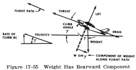
However what is significant for all airplanes, is that now there's a component of weight pointing aft along with drag, so thrust is not just pulling against the drag, but rather drag + the sine of the climb angle. Hopefully this makes it a little more intuitively easy to grasp why climb angle is only determined by excess thrust (i.e., thrust minus drag) and weight.
Hence the saying, with enough thrust lift is irrelevant...
https://upload.wikimedia.org/wikiped...ical_climb.png
https://upload.wikimedia.org/wikiped...ical_climb.png
Only half a speed-brake
One more question: When punching all the numbers into the FMS, to get the flex power setting, doesn't the system then also display the required distance from brakes release to rotation or T/O, so that the crew can do a sanity check whether the runway a head will suffice?
- runway physical characteristic and state: dry / wet
- obstacles under the pre-determined OEI lateral path
- wind, temperature and QFE
- TOW, flap setting and even CG
- perhaps some airframe deviations that may have a degrading effect.
- bleed and anti-ice configuration of the engine.
Somehow this is delivered to pilots, these days mostly run directly on the flightdeck by them. Results are the V-speeds (1, R, 2) and a temperature.
Speeds are bugged, and the temperature fed (via the FMS keypad) to the engine control units.
That resulting temperature is an assumed OAT, under which the take-off would be limiting.
To answer what was asked: Some of the modern software does have an option to display the margins of TODA / ASDA / etc. which would be there if it really was as hot outside as the resulting temp. Normally though, a sanity check is not done because the calc is run with a given runway as one of the inputs.
Only half a speed-brake
Vessbot Not in perfect agreement, mostly with the interpretation how that applies in our case but things may have gotten lost in translation.
Along these lines: if that aeroplane from the graphics had a better wing (longer L vector) it would climb faster - I really wish not to be wrong about that.
To make it climb steeper as it is, tilting the vectors, can only be achieved by adding more thrust to keep the equilibrium. No dispute there, the fact that showing throttles forward is needed to go up is not yet lost on this magenta child. There's hope yet
Similar to the extreme example of viper's temporary rocket dynamics, but on the other end: I think both of the above points need to be accepted to call our understanding complete - even before looking at a drawing where T = 1/4 L and the gamma angle is 1.4 deg.
Last edited by FlightDetent; 14th Aug 2019 at 20:46. Reason: Polished.
Join Date: Sep 2016
Location: USA
Posts: 803
Likes: 0
Received 0 Likes
on
0 Posts
For a certain weight, climb angle is proportional to excess thrust, which means thrust minus drag. Increase thrust, or decrease drag, and excess thrust is increased.
No matter the wing, L would have to exactly equal W cos gamma, no more no less. Any longer, and we would no longer be in equilibrium. (We would accelerate upward, yes, temporarily - a transient - but a better wing is not necessary for that: a longer L is already available, so long as we're not stalling, by merely pulling the yoke back. If we were already at Vx, then drag would increase, excess thrust would decrease, and we would either be forced to pitch down to capture the new slower speed and shallower climb angle, or naively hold the nose up and decay the speed until we stall). However, a better wing (i.e., better L/D ratio) would yield a steeper climb due its lower drag.
Not sure what condition you're fixing by the phrase "as it is," but to climb steeper (aka increase excess thrust), in addition to increaseing thrust, we can also decrease drag. Say we're starting from a fast equilibrium condition, way on the front side of the drag curve: climbing at a shallow angle (or flying level, or descending... it doesn't matter) at 300 knots. We pitch up a little bit, and slow from 300 to 250. Two things happen:
A) The transient - short term - L is greater than W cos gamma: We pitch up, accelerate upward, and slow down
B) The new equilibrium - long term - L is equal to W cos gamma: At the new slower speed, thrust is the same but drag is less, therefore excess thrust and climb angle are greater.
Both things have to happen, but it's waay too easy to only think about A. It seems deceptively obvious, as a part of the "vehicle goes where the nose is pointed" intuitive mentality that is so hard to break people out of, and it may seem like a waste of neurons to consider it past "duh, if you pull up you'll climb steeper;" but it's the wrong explanation (and a deadly one; aviation history is red with the blood of pilots who intuitively pulled up sans thrust, and their passengers). A is really only the mechanism by which B is established, and B is the real reason we're climbing steeper now.
To make it climb steeper as it is, tilting the vectors, can only be achieved by adding more thrust to keep the equilibrium. No dispute there, the fact that showing throttles forward is needed to go up is not yet lost on this magenta child. There's hope yet
A) The transient - short term - L is greater than W cos gamma: We pitch up, accelerate upward, and slow down
B) The new equilibrium - long term - L is equal to W cos gamma: At the new slower speed, thrust is the same but drag is less, therefore excess thrust and climb angle are greater.
Both things have to happen, but it's waay too easy to only think about A. It seems deceptively obvious, as a part of the "vehicle goes where the nose is pointed" intuitive mentality that is so hard to break people out of, and it may seem like a waste of neurons to consider it past "duh, if you pull up you'll climb steeper;" but it's the wrong explanation (and a deadly one; aviation history is red with the blood of pilots who intuitively pulled up sans thrust, and their passengers). A is really only the mechanism by which B is established, and B is the real reason we're climbing steeper now.
Last edited by Vessbot; 14th Aug 2019 at 21:33.
Only half a speed-brake
Vessbot I am sure we're on the same page, perhaps viewing from slightly different angles, like two people sharing a read would.
That graphic is maybe the first figure in all of the Principles of Flight books out there, and cannot be wrong. You will find a thread where I argued against several more experienced people that it is with thrust how I control sink rate and chase the G/S on approach, even on a swept-wing jet.
However, it describes a static state with constant speed and AoA (which is why the latter is missing in the depiction). An attempt to use it to explain what happens in different places of the envelope as you change from one to another would not work. There are full volumes of aerodynamic theory beyond this drawing for this very reason, the drag polar being just the first next one.
E.g. the graphics cannot explain the difference between Vx and Vy, and we both know how vitally important those are especially if someone finds himself well slow of both.
I had a bit of resilience accepting "Climb gradient is a function of excess thrust, nothing to do with lift." Took it the wrong way, not realising against the missing "For a constant speed and stable AoA,,.. " was there, just silent. Culpa maxima.
The climb gradient after takeoff has massive amounts to do with how much lift you have to begin with, and that depends on the speed (squared) at the beginning of the second segment. Sure, drag does too.
During the take-off performance analysis we can select the V2 speed higher above the low limit, closer up towards best L/D speed, which then yields a steeper climb with the same amount of thrust applied, over-ruling the drag increase.
Once airborne in the equilibrium state, all that ammo is gone and the basic principles take over - it is the thrust (excess or lack of) which defines the changes of the climb rate if we were keeping the airspeed steady. No disputing there.
I'll wait for your closing public remarks and then we really should continue elsewhere to avoid floggin'.
Last edited by FlightDetent; 15th Aug 2019 at 10:59.
Join Date: Jan 2008
Location: Herts, UK
Posts: 748
Likes: 0
Received 0 Likes
on
0 Posts
Crews started using adhoc quick-check acceleration times.with a stopwatch back in 70s at least AFAIK.
Surely the point is that with 3 crew cockpit, it wasn't a big issue.
And a rough check is all that's required... are we nominally accelerating as expected?
or not ?
if not quick check around...
Not exactly same as a V1 stop/go decision
Surely the point is that with 3 crew cockpit, it wasn't a big issue.
And a rough check is all that's required... are we nominally accelerating as expected?
or not ?
if not quick check around...
Not exactly same as a V1 stop/go decision
Join Date: Sep 2016
Location: USA
Posts: 803
Likes: 0
Received 0 Likes
on
0 Posts
Vessbot I am sure we're on the same page, perhaps viewing from slightly different angles, like two people sharing a read would.
That graphic is maybe the first figure in all of the Principles of Flight books out there, and cannot be wrong. You will find a thread where I argued against several more experienced people that it is with thrust how I control sink rate and chase the G/S on approach, even on a swept-wing jet.
However, it describes a static state with constant speed and AoA (which is why the latter is missing in the depiction). An attempt to use it to explain what happens in different places of the envelope as you change from one to another would not work. There are full volumes of aerodynamic theory beyond this drawing for this very reason, the drag polar being just the first next one.
E.g. the graphics cannot explain the difference between Vx and Vy, and we both know how vitally important those are especially if someone finds himself well slow of both.
I had a bit of resilience accepting "Climb gradient is a function of excess thrust, nothing to do with lift." Took it the wrong way, not realising against the missing "For a constant speed and stable AoA,,.. " was there, just silent. Culpa maxima.
The climb gradient after takeoff has massive amounts to do with how much lift you have to begin with, and that depends on the speed (squared) at the beginning of the second segment. Sure, drag does too.
During the take-off performance analysis we can select the V2 speed higher above the low limit, closer up towards best L/D speed, which then yields a steeper climb with the same amount of thrust applied, over-ruling the drag increase.
Once airborne in the equilibrium state, all that ammo is gone and the basic principles take over - it is the thrust (excess or lack of) which defines the changes of the climb rate if we were keeping the airspeed steady. No disputing there.
I'll wait for your closing public remarks and then we really should continue elsewhere to avoid floggin'.
That graphic is maybe the first figure in all of the Principles of Flight books out there, and cannot be wrong. You will find a thread where I argued against several more experienced people that it is with thrust how I control sink rate and chase the G/S on approach, even on a swept-wing jet.
However, it describes a static state with constant speed and AoA (which is why the latter is missing in the depiction). An attempt to use it to explain what happens in different places of the envelope as you change from one to another would not work. There are full volumes of aerodynamic theory beyond this drawing for this very reason, the drag polar being just the first next one.
E.g. the graphics cannot explain the difference between Vx and Vy, and we both know how vitally important those are especially if someone finds himself well slow of both.
I had a bit of resilience accepting "Climb gradient is a function of excess thrust, nothing to do with lift." Took it the wrong way, not realising against the missing "For a constant speed and stable AoA,,.. " was there, just silent. Culpa maxima.
The climb gradient after takeoff has massive amounts to do with how much lift you have to begin with, and that depends on the speed (squared) at the beginning of the second segment. Sure, drag does too.
During the take-off performance analysis we can select the V2 speed higher above the low limit, closer up towards best L/D speed, which then yields a steeper climb with the same amount of thrust applied, over-ruling the drag increase.
Once airborne in the equilibrium state, all that ammo is gone and the basic principles take over - it is the thrust (excess or lack of) which defines the changes of the climb rate if we were keeping the airspeed steady. No disputing there.
I'll wait for your closing public remarks and then we really should continue elsewhere to avoid floggin'.
If I'm reading you right, you agree that for steady states it's excess thrust that determines climb angle, and lift has no effect. And it's steady states that I was talking about, as I clarified in my last post. Also I was addressing your specific comment where you laid out a situation with a specific climb angle, pitch angle, and speed (V2) which is a steady state.
Actually, I think I found the remaining disagreement halfway through your post. At the risk of seeming flogging.... I hope you reconsider and come back, as why are we talking about flying on the internet to begin with?

Anyway, you seem to be treating the second segment climb, or flying at V2, as a transient condition and therefore not subject to the excess thrust rule. Now I'm treading into ground where I'm less sure than my previous posting in this thread, but I disagree with that too. It may not feel "steady state" as, depending on our SOP's we may only be holding that speed for a few seconds, some or all of which may be taken up by overshooting, corrections, etc. However, any of that is merely slop in execution, and real-life imperfections away from the platonic perfectly executed maneuver where we rotate exactly into the speed, freeze the pitch, and the speed then doesn't waver. If the thrust and speed are steady, then it's a steady state condition, and lift is irrelevant. It was relevant a few seconds ago in the pitch up (and vertical acceleration) off the runway and into the V2 attitude, but not once V2 is established.
Additionally, you bring up changes to V2, where it's selectable form a range. Then, it's the consideration of different steady state speed targets. You raise an example where we select a higher V2, closer to best L/D, that gives a steeper climb "overruling the drag increase," but actually the drag decreases, not increases in that case so there's nothing to overrule. Remember that the lowest drag is at best L/D, so by flying closer to it, we're flying at less drag, and thus in exact accordance with excess thrust yielding the higher climb angle.
Again, I hope you do come back, I'm thoroughly enjoying this discussion.
