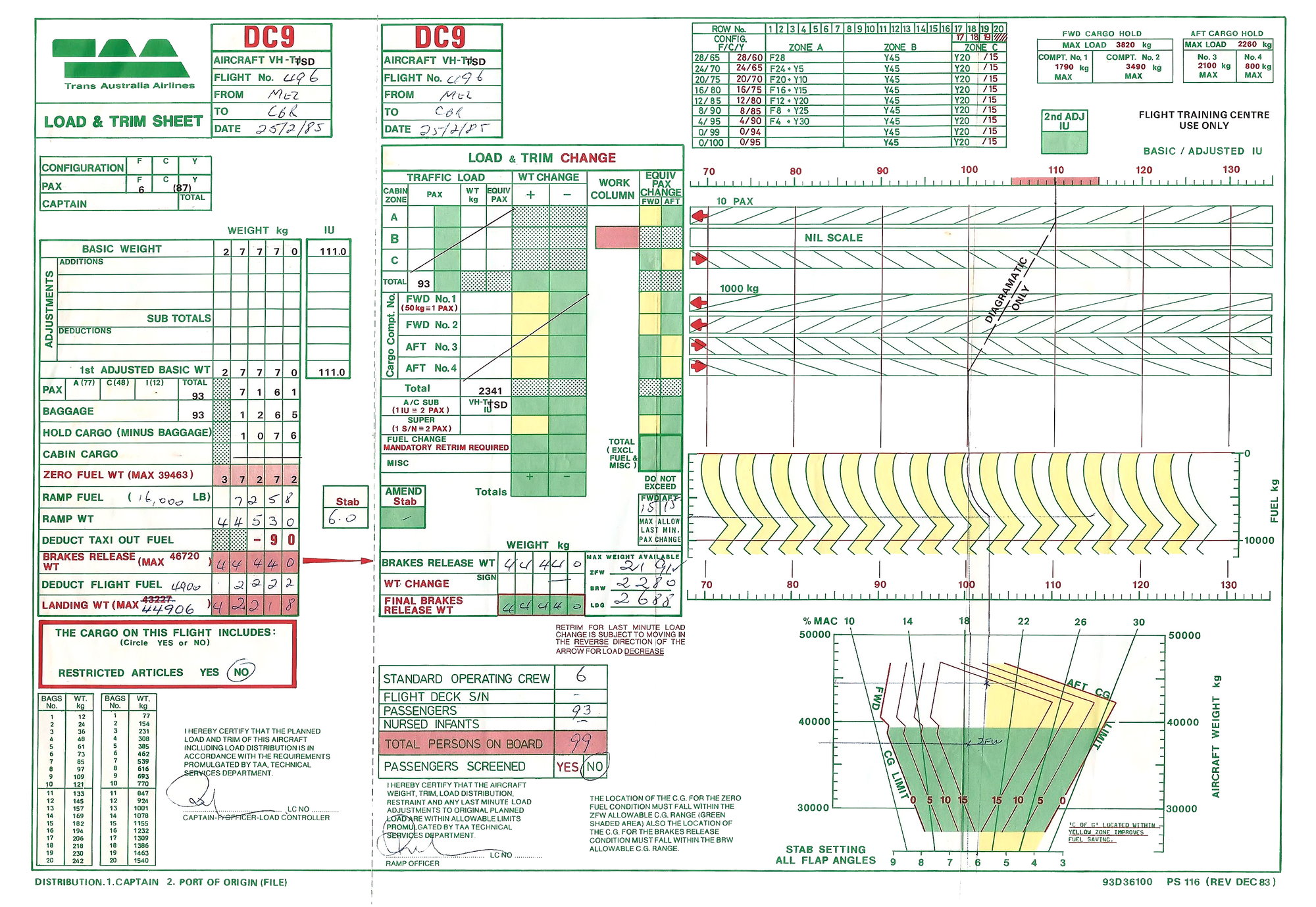
A DC-9-32 weight and loading chart. How to find the CG in % of MAC?

Thread Starter
Join Date: Feb 2017
Location: Bucharest
Age: 39
Posts: 20
Likes: 0
Received 0 Likes
on
0 Posts
Hello,
I'm not an airline pilot therefore I have no training in using or completely understanding these types of charts. What I am looking for in this document's charts is the center of gravity position limits as percentages of MAC, which I personally believe to be the reference that pilots need in order to prepare their plane for takeoff. All that I get from these charts seem to be some type of weights versus other type of weights. I was expecting to see one type of weight (either TOW or ZFW) versus CG position in % of MAC in order to find the optimum stab trim setting, but all I can find is a weight versus another, which personally doesn't make any sense to me for being a balance reference! Maybe I misunderstand it and I don't know yet how to "extract" the CG's position in MAC% from it! May someone please give me an idea what would it be useful with to have Actual ZFW versus Actual Index ZFW in a balance chart (I consider it a balance chart) in order to set up your trim?
Here's the chart which I'm talking about:
Thanks!

Never been on a dc-9, but the graph only shows the `Empty weight`,no pax /crew freight.
The `Zero fuel weight ` shows the Maximum weight with crew/pax/freight ..a structural limit..
The GW` shows the maximum permissible taxi/take-off weight permissible,not limited by other factors such as `runway ,air temperature or airfield altitude.
The figures at the top show the `Trim setting` for the tailplane for take-off..Other factors may modify that ,depending on flap settings possibly.
It is necessary to know where the basic `Datums ` for the Cof G to work out the MAC,,but that is not on this chart...
Moderator
What I am looking for in this document's charts is the center of gravity position limits as percentages of MAC
The chart presumably is part of a system with some tabular data to figure the numbers and then the data is applied to the chart. In general, a more complicated and error prone system than is optimal.
Observations -
(a) the datum is poorly chosen and is further forward than most designers would select.
(b) the chart is perfectly conventional in that the scales are gross weight against moment (index units). Given any two of weight, CG, and moment, the third quantity is calculated readily.
(c) the stab trim setting grid overlay is the MAC (ie CG) data you are after, albeit that it has been scaled directly to stab trim setting (which is why the line pilot wants to know the MAC, not for the MAC itself). However it is, nonetheless, the MAC grid. The AFM/WBM will have (a) chart(s) which give you the relationship between MAC and stab setting. I have plenty of background with the -33F but not this model so I can't help out with the specific data required there.
Caveat I don't have any -32 data to hand so I am making standard assumptions. If/when I get some data, some of the detail may need to change a little
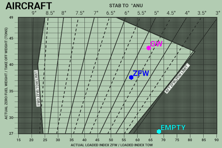
Hi, the coloured dots are a typical worked example.
Starting with Empty at 27 tonnes, you then add 10 tonnes of passengers and freight, to bring ZFW up to 37 tonnes. Then you can add the 6 tonnes of fuel, to bring the Gross Weight up to 43 tonnes.
As this Magenta spot lies within the envelope, you are within W+B. Then you can set the Trim to the take-off position.
As for % MAC the diagram does not contain MAC dimensions... You would need to know the width of the MAC.
The vertical axis is well marked in Tons. The horizontal axis I presume is in Inches (or centimetres.?).aft of datum position.
There is no simple %MAC that suites all (such as 20 to 35%.) or that would give an envelope with straight vertical edges..
Last edited by scifi; 25th Mar 2019 at 11:43.
Load sheet MAC
Iirc it was on the load sheet..we didn't need it, the important bit was the weight and stab trim setting.
Seem to remember that all of KSSU had the same paperwork which would have had a couple of graphs that we checked the MAC and then extracted the trim.
We would have made the decision on take off flap and EPR at the same time.
Was one of the nicest DC9s that I flew..the 51 would run out of elevator in the flare unless you wound the trim aft. 34 was another but possibly because of the fun lovely baliar cabin crew!
Moderator
Some comments re the previous two posts -
As for % MAC the diagram does not contain MAC dimensions... You would need to know the width of the MAC.
Not the case, I'm afraid, except to the extent required to draw the MAC fan grid.
Stab trim is related to the MAC in a one to one relationship as defined in the OEM AFM/WBM
The sheet designer has avoided going through the MAC grid scale and gone straight to the stab trim setting. However, the fan grid is, nonetheless, an MAC scale grid, regardless of the fact that it has been cast as stab trim. I presume that this model has (or the operator has decided to use) only one flap setting ? Normally, an aircraft will have multiple flap settings with different MAC-stab scale relationships. In this latter case, the MAC is plotted as the fan and then one will (usually) put the stab trim settings as separate scales for each flap setting. Otherwise it gets very messy trying to have multiple fan scales for each stab setting relationship.
The vertical axis is well marked in Tons.
Correct and absolutely stock standard.
The horizontal axis I presume is in Inches (or centimetres.?).aft of datum position.
Absolutely NEVER the case. On a trimsheet, the vertical scale is ALWAYS moment (or IU, more commonly - two ways of looking at moment). Please keep in mind that the envelope usually is presented in one of two layouts - weight x CG (which is the certification data) and weight x moment/IU (which is of use in calculations as we sum moments, not CGs).
There is no simple %MAC that suites all (such as 20 to 35%.)
Not the case. If the MAC grid is plotted as an overlay, you get the typical van-shaped grid. In this case, that is scaled as stab trim. However, it is just the MAC grid, rescaled to suit.
or that would give an envelope with straight vertical edges..
An envelope on a trimsheet with vertical fore and aft limits suggests that it has been (incorrectly) plotted as weight by CG and is ALWAYS a suspect design. Unless the curtailment analysis just happens to work out that way, it is presumed to be WRONG until proven to be correct. On the other hand, the usual weight by CG envelope in the AFM/POH will have (some) vertical limits. However, this is not the case for a moment envelope such as seen on ALL trimsheets (except the occasional example which has been drawn by a "designer" of little technical competence.
the important bit was the weight and stab trim setting.
Correct. While the FT fraternity is always concerned about MAC, the line pilot generally has no interest in the value beyond noting that the loading puts the CG inside the approved envelope at all stages during flight.
As these points are critical and indicate some incorrect training, I'll endeavour to find some model data and put an MAC overlay on the sheet to show how it works. Alternatively, if any of the posters have flown this sheet/aircraft model, perhaps you can email me some details for the particular aircraft.
If you want a good story (ie technically competent) regarding trimsheets, generally, there is a detailed thread on Bob Tait's pilot training website at https://www.bobtait.com.au/forum/rpl-ppl/5236-aircraft-trim-sheet-loading?limitstart=0
(The site moderator leading the discussion in that thread is a long standing Australian aircraft weights engineer with an extensive trimsheet design background.)
I assume that chart is for only one flap setting (hence no need to shown MAC, just Stab Trim).
Our loadsheet (similar type) has this at the bottom:

On ours, we get the MAC off the top of the graph then extract the Stab trim from the above table, depending on the flap setting.
Our loadsheet (similar type) has this at the bottom:
On ours, we get the MAC off the top of the graph then extract the Stab trim from the above table, depending on the flap setting.
Moderator
I assume that chart is for only one flap setting
Correct
On ours, we get the MAC off the top of the graph then extract the Stab trim from the above table, depending on the flap setting.
Quite standard. Generally, it is simplified by having the table shown recast so that it is integral with the trimsheet and one just runs into the table via the MAC value and interpolates for the stab setting. Given that the need for super accuracy is not all that critical for stab setting, this is more than sufficient for operational use.
Moderator
I've located some data for the -32. However, unless the curtailment for the OP's chart has been a little strange, it appears not to be consistent with the certification data. Perhaps the OP might post his full chart data to give us a better chance to make sure that the ID is correct ?
Thread Starter
Join Date: Feb 2017
Location: Bucharest
Age: 39
Posts: 20
Likes: 0
Received 0 Likes
on
0 Posts
Cheers!
Thread Starter
Join Date: Feb 2017
Location: Bucharest
Age: 39
Posts: 20
Likes: 0
Received 0 Likes
on
0 Posts
Never been on a dc-9, but the graph only shows the `Empty weight`,no pax /crew freight.
The `Zero fuel weight ` shows the Maximum weight with crew/pax/freight ..a structural limit..
The GW` shows the maximum permissible taxi/take-off weight permissible,not limited by other factors such as `runway ,air temperature or airfield altitude.
The figures at the top show the `Trim setting` for the tailplane for take-off..Other factors may modify that ,depending on flap settings possibly.
It is necessary to know where the basic `Datums ` for the Cof G to work out the MAC,,but that is not on this chart...
The `Zero fuel weight ` shows the Maximum weight with crew/pax/freight ..a structural limit..
The GW` shows the maximum permissible taxi/take-off weight permissible,not limited by other factors such as `runway ,air temperature or airfield altitude.
The figures at the top show the `Trim setting` for the tailplane for take-off..Other factors may modify that ,depending on flap settings possibly.
It is necessary to know where the basic `Datums ` for the Cof G to work out the MAC,,but that is not on this chart...
Thanks!
Thread Starter
Join Date: Feb 2017
Location: Bucharest
Age: 39
Posts: 20
Likes: 0
Received 0 Likes
on
0 Posts
Hi, the coloured dots are a typical worked example.
Starting with Empty at 27 tonnes, you then add 10 tonnes of passengers and freight, to bring ZFW up to 37 tonnes. Then you can add the 6 tonnes of fuel, to bring the Gross Weight up to 43 tonnes.
As this Magenta spot lies within the envelope, you are within W+B. Then you can set the Trim to the take-off position.
As for % MAC the diagram does not contain MAC dimensions... You would need to know the width of the MAC.
The vertical axis is well marked in Tons. The horizontal axis I presume is in Inches (or centimetres.?).aft of datum position.
There is no simple %MAC that suites all (such as 20 to 35%.) or that would give an envelope with straight vertical edges..
Starting with Empty at 27 tonnes, you then add 10 tonnes of passengers and freight, to bring ZFW up to 37 tonnes. Then you can add the 6 tonnes of fuel, to bring the Gross Weight up to 43 tonnes.
As this Magenta spot lies within the envelope, you are within W+B. Then you can set the Trim to the take-off position.
As for % MAC the diagram does not contain MAC dimensions... You would need to know the width of the MAC.
The vertical axis is well marked in Tons. The horizontal axis I presume is in Inches (or centimetres.?).aft of datum position.
There is no simple %MAC that suites all (such as 20 to 35%.) or that would give an envelope with straight vertical edges..
Thanks!
Thread Starter
Join Date: Feb 2017
Location: Bucharest
Age: 39
Posts: 20
Likes: 0
Received 0 Likes
on
0 Posts
I assume that chart is for only one flap setting (hence no need to shown MAC, just Stab Trim).
Our loadsheet (similar type) has this at the bottom:
On ours, we get the MAC off the top of the graph then extract the Stab trim from the above table, depending on the flap setting.
Our loadsheet (similar type) has this at the bottom:
On ours, we get the MAC off the top of the graph then extract the Stab trim from the above table, depending on the flap setting.
Cheers!
Thread Starter
Join Date: Feb 2017
Location: Bucharest
Age: 39
Posts: 20
Likes: 0
Received 0 Likes
on
0 Posts
I've located some data for the -32. However, unless the curtailment for the OP's chart has been a little strange, it appears not to be consistent with the certification data. Perhaps the OP might post his full chart data to give us a better chance to make sure that the ID is correct ?
Regards,
Mav.
Moderator
This is the only paper I've found regarding a DC-9's takeoff prep
Then do make sure that the model used and the one you are trying to model are the same - the numbers do differ between models.
Well, in order to actually fly you may still fly even slightly outside the graph (but with greater difficulty) with whatever stab,
While there is some fat in the MAC grid to stab setting relationship, the aim for the operator and crew is to set the stab as accurately as is reasonably achievable. The only residual errors should be associated with the (intentional) errors internal to the design of the loading system graphs (and, of course, any unfortunate and unintended loading errors on the day).
you normally set your stab according to the CG's position which lies at "X" MAC percentage
Correct and that is what is occuring in your graph - it's just that the designer didn't bother to indicate the MAC values which, at the end of the day, are only an intermediate step of no particular interest to the crew.
so I still don't know why do they use only weights as reference instead of CG position in order to set up your stab!
You appear not to be listening to the discussion. The graph fan grid IS the MAC grid relevant to the aircraft. It's just not scaled explicitly and there is absolutely no reason for it to be so scaled. With the relevant model AFM/WCM data, one, quite easily, could reverse engineer the thing and include the MAC values. Not sure why you would bother doing so but you could, should you so desire.
There is no C of G here, yes, so i was wondering if anyone might know how to extract it from this graph!
Again, the fan grid IS the CG (MAC) grid. With the AFM/WCM data, a very simple reverse engineering exercise to determine the CG values. Unfortunately, the only data I can find doesn't match the graph's data so we hit a barrier there ...
so if the horizontal axis may indeed refer to a longitudinal position taking the datum as reference, that may be converted into a CG position and subsequently into a MAC % position.
This NEVER can be the case. In a trim sheet, the scales will ALWAYS be gross weight by moment or IU (which are just different ways of looking at the same thing). This causes lots of heartache for folks as we see two styles of chart. In the limitations section the data, typically, is presented as weight by CG. In the loading system or weight and balance section, the data will be presented, usually, as weight by moment/IU or, for the inconvenience of having an extra bit of work, weight by CG. However, a trim sheet style of graph can ONLY EVER be weight by moment/IU - anything else is ALWAYS WRONG. If you want the CG values, that involves some extra calculation, in this case, a reverse engineering exercise.
something like this would've been very good for what I need
The usual presentation is to run the MAC fan lines up to the top of the graph and then overplot with separate stab setting lines to suit each flap setting.
but that chart which misses the C of G reference is all I have
As I suggested earlier, the TCDS data for the referenced model doesn't quite match the graph very well. If you can find the data upon which the graph was designed, we can reverse engineer the data you seek .. very quickly.
I think it would help your understanding, greatly, if you had a look through the thread hyperlinked at post #7. That thread provides a very comprehensive overview of trimsheet design problems.