


Turbojet Axial Rotor Thrust - SR-71

Thread Starter
Unless we can get some traction on my OP I'll delete the thread. The link provided by Turbine D at #18 provides all the information that Concours77 is derailing this thread with.

It isn't nice to the readers or other posters for the OP to delete their thread in a technical forum. It's like my Prof tearing up my exam book as not worth anything since it will never make an "A" grade.
I have the POH for the SR71 and though it mentions spike position it doesn't say anything about this subject..My feeling is unless a very old or dead P&W engineer or a Habu who has flown it, comments, the fairest answer is that nobody knows
Last edited by Pugilistic Animus; 9th Sep 2018 at 07:05.
Join Date: Jul 2014
Location: Germany
Posts: 344
Likes: 0
Received 0 Likes
on
0 Posts
Is this merely indicative that most of the compression is coming from the inlet rather than the compressor?
Regarding the thrust load i get the impression we need to clarify what the rotor is, i would assume it's the complete rotating spool of the engine yes?
In normal operational circumstances of a turbojet I'd expect a fairly large axial drag component on the rotor (negative thrust if you like, since the turbine is driving the compressor)
That's equal to the combined aerodynamic axial load of compressor and turbine.
Turbine will be pulled backwards and the compressor will be pulled forwards.
Now why would you expect a large axial drag component?
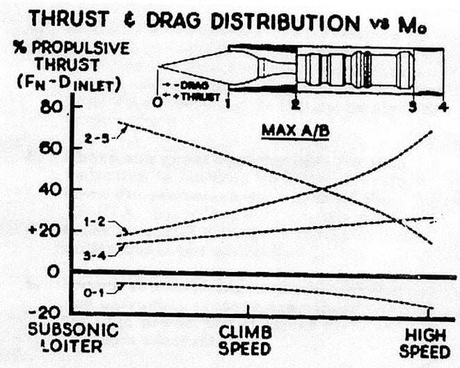
Check the picture on this page: http://aeromodelbasic.********.com/2...bution-of.html
Edit: why would this forum censor ********? anyway via link shortener http://goo.gl/RbZFpY
Now if you shove air down the compressor as in the SR71 the forward thrust load on the compressor reduces so that the forces on the spool eventually sum up in the other direction.
The overall forces as described in the picture still need to sum up as a force thats forward for thrust to be produced. But there are forward components on other parts of the engine that take care of that.
If any turbojet is at idle or while the aircraft is at high speed i would also expect the thrust load on the rotor to become negative.
This could still happen while the engine as a whole is producing thrust as the combustion chamber for example is being pushed forwards while the rotor is being pushed backwards a bit.
Anyhow clarify what exactly it is you are asking or what you are not clear about and i'm sure there will be some more answers.
Last edited by wiedehopf; 9th Sep 2018 at 23:57.
Notwithstanding OP’s query, there is a wealth of discussion on the recommended thread (thanks TurbineD)
In my opinion, it answers point proffered in this thread, from lomapaseo and wiedehopf Both, and I conclude without doubt that the engine/airframe in question here, the SR-71, is a Ramjet powered aircraft. In fact, it is by definition powered by partial contributions of three distinct power plants: Turbojet, Ramjet, and “transitional”. (Hybrid).
To realize the nature of this airplane is to have to confess to awe. Nothing short of pure aeronautical genius......
concours
Well that opens up a more involved discussion. I suspect that with the much lower Mach and the technology of the day, that the Concorde had a much simpler inlet and less opportunity to recover thrust.
Lower Mach and mission requirements and so on surely helped, but I thought Concorde's Olympi (or Olympuses or whatever) were ranked as the most efficient engines ever at pressure recovery - something like 94%. And the inlet design slightly beat the SR-71 by producing 85% of the thrust (vs. 83% for the Blackbird.)
If I have my facts approximately right, SR-71 could sustain Mach 3 for 90 minutes with afterburners and occasionally supercruise at Mach 1.5 without AB, Concorde could sustain Mach 2.02 in supercruise (no afterburner/reheat thrust) for around 180 minutes (London-Bridgetown, and occasionally, if the winds/weather and weight were right, Caracas-Paris).
The Blackbird was actually the "older technology" (first flight 1964, A-12 1962) although the core strategy (no pun intended) was the same, just different engineering tactics (ramps vs. spikes, etc.), and more or less concurrent with Concorde. And both brilliant.
Save Concorde Group � Engines
Last edited by pattern_is_full; 9th Sep 2018 at 22:15.
Thread Starter
Originally Posted by Concours77Ad hominem is an admission of ignorance.
Now comes the controversy. The inlet is claimed to provide fifty four percent of the thrust.
Where does it provide this thrust? Not at the inlet. Not in the engine, not in the exhaust.
In the Ejector. Total thrust is measured at the rim of the fully open Ejector.
Where does it provide this thrust? Not at the inlet. Not in the engine, not in the exhaust.
In the Ejector. Total thrust is measured at the rim of the fully open Ejector.
It isn't nice to the readers or other posters for the OP to delete their thread in a technical forum. It's like my Prof tearing up my exam book as not worth anything since it will never make an "A" grade
at my school if your paper didn't answer the question you received 0%, I realise schools these days believe everyone deserves a medal, any indication of failure having dire consequences on ego. As for deleting the thread, one poster is hijacking it with superfluous information that can be found on Blackbird's thrust questionand not addressing the OP. Waste of bandwidth.
If the OP were to judged on-topic responses then I suspect that there is an agenda rather than a question of learning something of benefit for the rest of us.
Thread Starter
The only agenda is to get an answer to the question posed. All else covered by others on this thread not answering the question is more than adequately covered on Blackbird's thrust question I suggest you post there if you wish a discussion, this thread is about a very specific aspect, axial-rotor-thrust. Sorry.
That question is exactly what is discussed in the reddit link i posted. So it was perfectly on topic.
Regarding the thrust load i get the impression we need to clarify what the rotor is, i would assume it's the complete rotating spool of the engine yes?
Now we are discussing the direction/magnitude of the load on the thrust bearing of the spool of a turbojet.
That's equal to the combined aerodynamic axial load of compressor and turbine.
Turbine will be pulled backwards and the compressor will be pulled forwards.
Now why would you expect a large axial drag component?
Check the picture on this page: http://aeromodelbasic.********.com/2...bution-of.html
Edit: why would this forum censor ********? anyway via link shortener model aircraft: Thrust distribution DISTRIBUTION OF THE THRUST FORCES
Now if you shove air down the compressor as in the SR71 the forward thrust load on the compressor reduces so that the forces on the spool eventually sum up in the other direction.
The overall forces as described in the picture still need to sum up as a force thats forward for thrust to be produced. But there are forward components on other parts of the engine that take care of that.
If any turbojet is at idle or while the aircraft is at high speed i would also expect the thrust load on the rotor to become negative.
This could still happen while the engine as a whole is producing thrust as the combustion chamber for example is being pushed forwards while the rotor is being pushed backwards a bit.
Anyhow clarify what exactly it is you are asking or what you are not clear about and i'm sure there will be some more answers.
At a certain Airspeed, the Pressure on the Compressor end of the rotor is rearward, and of equal value to the thrust moment forward.
It is at this condition that the rotor “floats” in its thrust bearings, net thrust (on the rotor) is neutral?
Increase the Airspeed more, and the inlet pressure becomes dominant. The net thrust on the rotor is rearward (aftward).
Is that it?
Question. At the face of the compressor, is there a point where the inlet air is at such pressure that the compressor is driven by the inlet, and morphs into a turbine? If so, do we expect there to be a neutral point where the compressor blades can accurately be described as stators? That would be a complicated answer due to increasing angle of attack of the blades in sequence?
Where is the inlet drag, (pressure) expressed as thrust? It is dominant, per megan’s OP, fifty four percent of total. At high cruise, most of it is dumped into the Ejector, to be heated, expanded and ejected as thrust?
Here to learn.
concours
apropos not much: “took my girl for a ride in the Skylane. She pointed to.an instrument on the dash. “What’s that? Everything looks so complicated.” The pilot in me wanted to Say ‘Chronometer’. I had to say instead, ‘’honey, that’s a clock...’
“If this description of "thrust" is mostly true for structural calculations, I find it strange it was
The inlet produces no thrust until the gas contents escape.
Last edited by Concours77; 10th Sep 2018 at 15:04.
Join Date: Dec 2010
Location: Europe
Age: 88
Posts: 290
Likes: 0
Received 0 Likes
on
0 Posts
@ Concours
This might help you understand what forces act where
@ Megan
Given the typical distribution of internal forces in a simple single spool jet, it is difficult to see how the remark you are questioning could refer to anything other than the complete compressor/turbine spool
Check your PMs
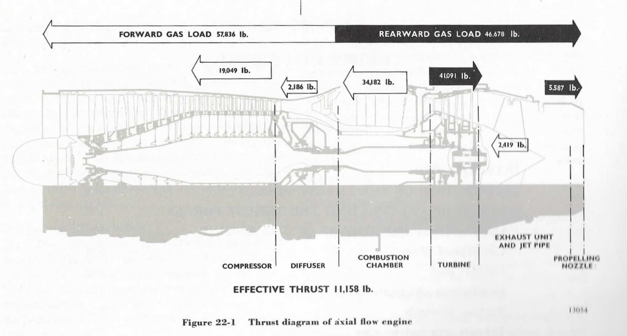
This might help you understand what forces act where
@ Megan
Given the typical distribution of internal forces in a simple single spool jet, it is difficult to see how the remark you are questioning could refer to anything other than the complete compressor/turbine spool
Check your PMs
An honor to be addressed personally by you sir. Thank you
I accept: The engine is an integrated system. Only with caution should we simplify by “dividing” the whole into “zones.”
Breaking down the dynamic system into “partial thrust values” in my opinion suggests that “Thrust” is created within that zone. Is that right? Because, the gas “load” suggests only where the “effects” of thrust occur.
i am perfectly comfortable with the diagram. Zone 1-2 “feels” the most thrust, while the zone 2-3 feels second most thrust. The structure that “experiences” the bulk of thrust I take to be the aft portion of the sloping centrebody.
The structure acting as the Newtonian wall (“reaction”) is the inner forward portion of the combustion chamber?
It is tempting to say that the loads are assigned by position and distance from exhaust. The ultimate impinged structure is the furthest from the efflux, imo. The Inlet.
Another thing. Single spool integral rotating mass, the “rotor”. Related to the original question, is it permitted to entertain this rotor as “floating” in its thrust bearings, when the axial aerodynamic loads are equal? (Compressor, Turbine).
Best to you,
John
OK, it took two hours and twenty minutes....
hallelujah...got it. Forever in your debt CliveL.
Last edited by Concours77; 10th Sep 2018 at 23:11. Reason: The Eureka
Single spool integral rotating mass, the “rotor”. Related to the original question, is it permitted to entertain this rotor as “floating” in its thrust bearings, when the axial aerodynamic loads are equal? (Compressor, Turbine).
This is a direct comment to his (OP) question about axial reversal?
(Btw, are these thrust bearings similar to the Trent-9 ball bearings?)
concours
The thrust bearings are typically ball bearings. The only time I heard of conical rollers were the very old RailRoad adds of the 40's. Things go tits-up when a cage breaks and the balls migrate away from the radial load. Fortunately the shafts find a home cuddling inside some other bearing compartment until the plane lands.
It's like a bowling ball inside a washing machine. Best not to be in the same room with it.
It's like a bowling ball inside a washing machine. Best not to be in the same room with it.
If the purpose was to tease out some conjecture, (and I have no way of knowing...), I’ll offer some thought.
The purpose of propulsion is to meet and overcome drag, with enough left over to accelerate the airframe.
A percentage of inlet air is continuously dumped (evacuated) from the dorsal airframe bleeds. That shows the design is competent in regards to drag, thrust, and excess power.
The rotor, compressor, and turbine are functionally integrated in a solid structure. Conceivably, with sufficient drag at the inlet, this propulsive design could operate as Ramjet, prior debate notwithstanding.
If it did, it would demonstrate the reversal of axial thrust at the rotor. The inlet air would exceed in Force the effort of the turbine, and force the rotor forward, into its thrust bearings with forward force. At this point in the transition to our ramjet, the turbine and its compressor adjunct would be superfluous, even deleterious to the engine’s current “configuration”. The inlet (drag) overpowers the aft turbine, driving the compressor and reversing output of the turbine.
The inlet stators have trailing edges that articulate from “adding camber” to “free stream” at high engine output; the swirl contribution is unnecessary at high speed.
Imagine that the compressor blades and turbine could be “subtracted” from the design in transition to pure Ramjet? If not remove, then “feather” the blades.
Make no mistake, that is exactly what the six bypass tubes accomplish, only partially. Bypassing the bulk of the compressor, the diffuser, the combustion chamber, and dumping inlet air directly into the afterburner section, it is a “partial” ramjet system.
If correct, I am sure this is not new to the OP. But it is new to me, just trying to catch up to those further along the learning curve.
much respect to megan,
concours
Join Date: Dec 2010
Location: Middle America
Age: 84
Posts: 1,167
Likes: 0
Received 0 Likes
on
0 Posts
Concours77,
You are making this discussion much more complicated than it needs to be. Pratt had a problem with the initial engine design. A solution to that problem was identified and patented. It worked. It worked because of understanding what was taking place inside the engine that had to be modified. It had nothing to do with inlet stator trailing edges or feathering blades. Follow along this summary of the problem and solution:
A turbo-ramjet engine is exactly that, a turbojet working together with a ramjet to power an aircraft to Mach 3+ that could not be achieved independently of one another. To simplify this, A ramjet generates no static thrust and needs a booster to achieve a forward velocity high enough for efficient operation of the intake system. The turbojet is the booster. Ramjets generally give little or no thrust below about half the speed of sound, and they are highly inefficient until the airspeed exceeds 1000 km/h (600 mph) due to low compression ratios. The turbojet is very efficient in this regime. Ramjets work by ingesting relatively low speed air and expelling the air at a higher speed. The difference in speed results in a forward thrust. The burning fuel creates higher pressures inside the engine, causing higher exhaust speeds. But the thrust of the engine depends entirely upon how much air flows through it. No matter how hot the burning air-fuel mixture is, and how high the pressure, if not much air flows into the front of the engine not much thrust is produced. So the trick to improving ramjet efficiency is to increase airflow through the engine. This is accomplished by the spike or obstruction called an innerbody. It is pointed on both ends and thick in the middle and fits inside the intake tube. Air passing into the tube must flow around the innerbody, and the area around it is less than the area of the intake opening. Consequently the air is compressed as it flows around and reaches a maximum pressure in the narrow throat between the innerbody and the intake tube. The same amount of air flows into the engine, but it is raised to a higher pressure. This increases the pressure that the burning gasses must push against, causing the overall pressure inside the tube to increase. Higher internal pressures mean greater amounts of air in the engine, so more fuel can be burned. The result is still higher pressures, increased exhaust gas speed, and greater thrust. But there is a problem that must be dealt within the turbojet compressor area. When the pressure becomes too high in the compressor, the rotating blades tend to flutter, may break, the compressor can stall and the high temperatures can result in mechanical failures. So the P&W designers cleverly bled off air from the compressor to lower the pressure and temperature and fed it back to the burner in the afterburner section through the magical bypass tubes, it worked extremely well.
The way I approach learning is to take data in, rearrange it, and try to improve my understanding. One effective way to store it is to write about it, and see how it looks. I am not a teacher, I suck at teaching, the best I can do is try to understand what has gone before.
I really don’t care about how I look: bright, posturing, wanna be, whatever, my purpose is to increase my knowledge. I am essentially writing papers; megan was prescient when she answered lomapaseo with a “classroom” rubric.
Selfish? I don’t think so. I am taking a risk when I post here; looking or being read as stupid takes second place to my personal increase in knowledge.
best Regards,
John
Last edited by Concours77; 12th Sep 2018 at 15:27.