


How does a short HF antenna on an Airbus transmit/receive such long wavelengths?

Thread Starter
Join Date: Aug 2017
Location: London
Posts: 6
Likes: 0
Received 0 Likes
on
0 Posts
How does a short HF antenna on an Airbus transmit/receive such long wavelengths?
What type of witchcraft are engineers using for a very short antenna in the leading edge of a tail fin, to be able to receive and transmit on HF?
When doing my ATPL studies many years ago, the information was rather superficial on HF equipment.
Let's say the frequency we are tuned to is 9000 khz or 9 mhz. That equates roughly to a wavelength of just over 30 metres.
Even if the antenna were a quarter wavelength long, it would still need to be over 8 metres in length - yet the antenna is much shorter than that.
So how is this trickery done? Are they using the entire tail fin for radiating/receiving? In which case the "antenna" referenced in my FCOM isn't really an antenna at all, it's just a tuning unit.

Join Date: Jul 2008
Location: Skating away on the thin ice of a new day.
Posts: 1,116
Received 13 Likes
on
8 Posts
An antenna is just a fancy tuned circuit. If the antenna is the wrong length, a tuner (coupler in aircraft HF as it is at the antenna feed point) is used to balance the capacitance and inductance as required.
Last edited by ampclamp; 20th Aug 2017 at 00:12.
Join Date: Sep 2007
Location: UK
Posts: 11
Likes: 0
Received 0 Likes
on
0 Posts
The preferred length of an antenna is a half wavelength but those are often not practical either for space reasons or because multifrequency working would require variable length antennas.
Quarter wave antennas work well if they are mounted on a large conducting surface because that surface mirrors the quarter wavelength to provide the half wavelength total.
In practice any length can be made to work if you have a tuning unit to resonate it although short antennas are less efficient than full-length ones. As an example, the long wave transmitter at Droitwich in the UK has an antenna a fraction of a wavelength long but it still manages to cover a large chunk of the UK and France.
So an antenna a few metres long may be well below the ideal length but can still be made to work. I've had 200 mile distance contacts on amateur radio from a car with a 2m long antenna at 1.8MHz (160 metre wavelength).
The downside of short antennas is that you end up with very high voltages involved even at modest power levels and that tends to be limiting once arcing starts to occur.

Join Date: Dec 2013
Location: Norfolk
Age: 67
Posts: 1
Likes: 0
Received 0 Likes
on
0 Posts
It may help to think of the antenna as just a device to couple the radio waves coming out of the transceiver at an impedence of typically 50 Ohms to the impedence of free space which is approximately 377 Ohms. This is to ensure radio waves are emitted as efficiently as possible. I should point out that this idea is an absolute heresy to many, but the true technical explanation is rather too complex and mathematical to go into on this forum.
This can be accomplished by having wires of a specific length for a given frequency, or by using capacitors and inductors to electrically alter the apparent length of the wire. The lower the frequency, the longer the wavelength and the more wire you need to make a tuned antenna. The transceiver doesn't care what it is transmitting into so long as it has the right impedence i.e. it is tuned correctly for the frequency in use. An impedence mismatch will effectively reflect power back into the output stages of the transmitter section and cause overheating of components and failure.
Technically there is no reason why the impedence of a transceiver couldn't match the impedence of free space, thus allowing a suitable length of wire to be connected directly to the antenna socket. The problem is that for each frequency used, the wire length would need to be altered. The 50 Ohm impedence is just an industry standard that has evolved so that equipment from different manufacturers can be interconnected without too many problems. It is easier to design electrical circuits to artificially lengthen or shorten a wire than to use a mechanical system to do the same thing. Early aircraft fitted with radio equipment did trail long wire antennas that needed to be wound out after takeoff and retrieved before landing. These wires frequently broke in flight preventing communication between the aircraft and ground stations.
In order to efficiently radiate a signal, the general rule is the bigger the antenna, the bigger the signal you will put out.
Modern transceivers can generate very high power levels and have very sensitive receivers, so the actual antenna size is less relevant now than in the past.
Antennas can also be designed to be directional in that they radiate (or receive) signals in a specific direction or pattern rather than omnidirectionally. That can also increase the efficiency of the system by limiting radiation of signals in directions that are not necessary.
Receivers can be designed to be so sensitive that a metre long antenna will pick up signals from around the globe. The sensitivity is so great that antenna impedence mismatches are virtually irrelevant. The same cannot be said for transmitters. In order to reliably transmit a signal any significant distance you need a large antenna, or a powerful transmitter. That said, very low power equipment is capable of global communication under the right conditions on short wave frequencies. One of the reasons why radio users are required to be licensed according to international regulations because of the potential for causing widespread interference if equipment is operated incorrectly.
Last edited by G0ULI; 20th Aug 2017 at 02:37.
Chief Tardis Technician
Join Date: Jan 2001
Location: Western Australia S31.715 E115.737
Age: 71
Posts: 554
Likes: 0
Received 0 Likes
on
0 Posts
The coupler/Antenna tuner has a bunch of high voltage capacitors and inductors (coils of wire) and s couple of stepper motors. The magic internals get the motors to move wiper arms around until the apparent impedance of the antenna measures up correctly..
I once found the feed wire on a huey had broken off inside the tail boom and had a length of about 8 inches, but the HF worked perfectly. The break was repaired, and the HF went back to its usual crap performance....
I once found the feed wire on a huey had broken off inside the tail boom and had a length of about 8 inches, but the HF worked perfectly. The break was repaired, and the HF went back to its usual crap performance....
Guest
Posts: n/a
In my snotty nosed "yoof" period at Locking I seem to remember this little gem being called a Balun. (Of which there are at least 4 different types).
Used where the RF half wave characteristics ( λ/2) of the antenna are not correctly matched to the impedance of the coax or transmission line. Some transmission or reception loss occurs but if correctly calculated and tuned can reduce the losses to approaching 1/1.
Used where the RF half wave characteristics ( λ/2) of the antenna are not correctly matched to the impedance of the coax or transmission line. Some transmission or reception loss occurs but if correctly calculated and tuned can reduce the losses to approaching 1/1.
I don't own this space under my name. I should have leased it while I still could
Such short notch aerials have been around since the 50s. The Vulcan had one such aerial in the base of its fin. You can see this in photographs as a paler green dielectric panel. The aerial itself had to be pressurized. As with such older designs, little thought had been given to ease of access.
Join Date: Oct 2016
Location: Horsham
Posts: 27
Likes: 0
Received 0 Likes
on
0 Posts
There is a lot more going on in the antenna tuner but basically if the antenna is too short the tuner "adds" wire by increasing inductance. Conversely if the antenna is too long capacitance is added.
It's not as simple as just adding one component, there is some really clever impedance matching that goes on as well.
It's not as simple as just adding one component, there is some really clever impedance matching that goes on as well.
Last edited by XL189; 20th Aug 2017 at 21:35. Reason: bad grammer
Thread Starter
Join Date: Aug 2017
Location: London
Posts: 6
Likes: 0
Received 0 Likes
on
0 Posts
I'm impressed by the excellent responses. Thanks everyone! You've given me plenty of food for thought.
Would that be achieved by having a Banun or UNUN located between the antenna and coupler?
The 50 Ohm impedence is just an industry standard that has evolved so that equipment from different manufacturers can be interconnected without too many problems
Join Date: May 2011
Location: Hampshire
Age: 76
Posts: 821
Likes: 0
Received 0 Likes
on
0 Posts
And who remembers those calculations when you were asked to work out whether the V or the I was greater at the ends etc?
While serving with the South Wales Borderers in Botswana providing HF comms to the outside world, the Company Signals Sgt came to me, asking for a coax adaptor or termination of some sort. I asked him what was he intending to do with it and he said he was going to use a rhombic antenna to maintain comms back to the Company HQ during the upcoming safari into the Botswana bush. He had done simple signaller's training and some idiot had mentioned rhombics to him. He didn't want to listen when I explained the difficulties he was making for himself so let him get on with it, wondering where he as going to get the miles of wire for his 2MHz and 6MHz links. My oppo, the "other radio tech" went with them and after watching this poor bloke struggling with setting up a working aerial, he took a legth of wire, tied on end into the ring on the handle of an adjustable spanner and threw it up a tree. Worked a treat!
While serving with the South Wales Borderers in Botswana providing HF comms to the outside world, the Company Signals Sgt came to me, asking for a coax adaptor or termination of some sort. I asked him what was he intending to do with it and he said he was going to use a rhombic antenna to maintain comms back to the Company HQ during the upcoming safari into the Botswana bush. He had done simple signaller's training and some idiot had mentioned rhombics to him. He didn't want to listen when I explained the difficulties he was making for himself so let him get on with it, wondering where he as going to get the miles of wire for his 2MHz and 6MHz links. My oppo, the "other radio tech" went with them and after watching this poor bloke struggling with setting up a working aerial, he took a legth of wire, tied on end into the ring on the handle of an adjustable spanner and threw it up a tree. Worked a treat!
Join Date: Dec 2013
Location: Norfolk
Age: 67
Posts: 1
Likes: 0
Received 0 Likes
on
0 Posts
Teapot Rebellion
A balun or unun stands for balanced to unbalanced, or unbalanced to unbalanced coupler. Typically a balun is used when connecting an unbalanced coaxial cable to a balanced antenna such as a dipole, which has two equal quarter wavelengths of wire at the desired frequency. These devices are usually made up of a ferrite core with two sets of windings, one to the transceiver and one to the antenna. The balun helps prevent the outer sheath of the coaxial cable from picking up the transmitted signals and feeding them back into the transmitter, depending on the length of the coaxial cable being used. By varying the ratio of turns, they can also be used for impedence matching. A single winding may also be used and connected as an auto transformer.
So essentially a balun or unun is just a transformer used to couple or connect the transceiver to the antenna cable. The ARRL and RSGB internet sites contain detailed information on use and construction of these devices.
Join Date: May 2010
Location: Boston
Age: 73
Posts: 443
Likes: 0
Received 0 Likes
on
0 Posts
The 50 ohm standard is related to efficient geometry for coax cable.
There is a sweet spot where the various losses tend to balance out at a minimum.
Common to see both 50 Ohm(RF) and 75 Ohm for tv and video
For balanced transmission lines (aka twin lead) 300 ohm is common which (may) in part explains 75 Ohm for video since one simple balun design results in a 4:1 ratio.
It's this sort of discussion that really rams home how little I really know about electronics and radio gear.
Fascinating stuff.
Fascinating stuff.

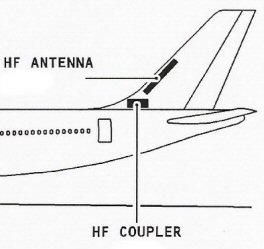
The way it was explained to me by an engineer who appreciated he was talking to a pilot, is that the shunt acts as an exciter which allows the whole fin to become the HF aerial. The coupler also matches the rest of the airframe to the shunt to act as the ground plane. In effect, the whole aircraft is the HF aerial. When pilots write up the HF as being poor, the engineers test them on the ground where often the aircraft is properly earthed - which is often the cause of the problem. No fault found!
Join Date: Jul 2014
Location: Germany
Posts: 344
Likes: 0
Received 0 Likes
on
0 Posts
@busta level
with radio transmissions the signal/noise ratio is very important.
assuming your receiver circuitry is sufficiently sensitive and it's own noise floor is quite low the only important factor is the SNR of the signal in the air.
so when the ground station transmits with its powerful transmitter the HF signal noise is low compared to the signal thus you get good reception.
but on transmission your effective power for getting signal into the air might be insufficient and the ground station picks up lots of HF noise because it needs to increase gain.
now i don't know if it has to do with the airplane having less metal or the transmitter just being lower power or whatever. but lower effective transmission power might sure be a possible scenario.
Join Date: Dec 2013
Location: Norfolk
Age: 67
Posts: 1
Likes: 0
Received 0 Likes
on
0 Posts
It is important to realise that there is a difference between electrical isolation and radio frequency isolation. Electrical isolation merely means that two conductive materials are separated by some imsulating material. At radio frequencies it is possible for seperate and electrically isolated conductors to pick up radio frequency energy from one another. Several antenna designs such as the Yagi antenna have director and reflector elements that are electrically isolated from one another. All the beam shaping is done with isolated pieces of metal arranged along a boom. Analogue (and digital) TV aerials are a typical example of this type of antenna.
The difficulty of designing efficient antennas for aircraft or satellites is that the antenna either has to have two equal sections working against each other such as a half wave dipole, which is made up of two quarter wavelength wires attached to the inner and outer conductors of a coax cable respectively, or the transmiting element needs to operate against a ground plane.
So while on the ground the earth itself acts as half of the antenna, but as soon as you get up in the air some part of the aircraft needs to become a replacement for the ground in an unbalanced antenna system. The tail of the aircraft can become the radiating element and the wings or body a replacement for the earth. Even in composite bodied aircraft there is enough metalwork to perform this earth function.
Unfortunately the demands of lightning protection mean that all parts of the aircraft need to be electrically bonded together, so it is difficult to find a large isolated panel,or area that can be easily used as a radiating element. The tail fin is generally the best compromise being at the back of the aircraft and away from many sources of electrical noise and interference.
The down side is that conductive dirt layers can build up bridging the electrical isolation of the antenna radiator section due to deicing operations, salt laden atmosphere, rain and general ageing. This reduces the efficiency of the antenna and can allow the introduction of electrical noise from elsewhere in the aircraft. Rain and hail in particular can carry static electrical charges that will absolutely wipe out short wave signals for as long as the rain or hail persists. The only thing that can be heard is a loud crackling noise.
Aircraft should be kept clean and the correct precautions taken when repainting to avoid bridging any electrical isolation areas. Similarly the electrical connections between "earthed" areas of the aircraft need to be kept clean to maintain a low resistance path.
It is a sad truth that most electrical faults end up being traced back to a mechanical origin. The most useful instruments for an electrical engineer are a good pair of eyes and a keen sense of smell (for burnt out components). All the meters and test gear tend to play a secondary role.
It is surprising how often the old, "try unplugging it and plugging it back in again" works too! The reason for this is that a fine insulating oxide layer can form on plugs and sockets. Unplugging and plugging equipment back in scrapes away the oxide layer and completes the electrical path once more.
@Gouli and others: Good posts.
Thread Starter
Join Date: Aug 2017
Location: London
Posts: 6
Likes: 0
Received 0 Likes
on
0 Posts
I'm not sure if I understand the difference between a counterpoise and a ground plane. Is the following correct?
A counterpoise is used as a substitute when direct earthing is not available, to increase the potential difference through capacitance. That I presume can only be used on land based antennas?
A ground plane is used for reflecting the radio waves. For example, if a 1/4 wavelength antenna is used, a 1/4 length ground plane is used to give a 1/2 wavelength.