


Concorde question

Join Date: Jan 2008
Location: FL 600. West of Mongolia
Posts: 463
Likes: 0
Received 0 Likes
on
0 Posts
ChristiaanJ
aaah yes, Max Climb/Max Cruise modes. I'd not forgotten this my friend, I was going to say a few words about that in a future post, but maybe we can do that now. (And I'd love to hear more of your comments on this here too, ChristiaanJ). The intake and autopilot modifications were in a way complimentary it's true, but really dealt with separate problems, at least in my view:
The intake control unit software change (a change to the control law that limited engine N1 as a function of intake local Mach number, Mo, and inlet total temperature, T1) was able to put an absolute limit on aircraft achievable Mach number during Mmo overshoots, but it would not PREVENT Mmo overshoots occurring altogether, it was more of a safety brake. This particular overspeed problem manifested itself well before route proving, and in fact the intake system 'fix' resulted in the Thrust Auto Reduce System being deleted, electronic control boxes and all. The TAR system was fitted on all development aircraft equiped with the digital intake system, and it tried (in vain) to limit extreme Mach overshoots. The production aircraft retained the TAR wiring and locked out circuit breakers, as well as two vacant spaces on the electronic racks. The prime reason for all these efforts were that some of the rapid excessive Mach overshoots quite often drove the intake into surge; the modification to this N1 limiter control enabled engine mass flow to be controlled in such a way that these surges could be prevented during temperature shears. The aircraft Mach limit was an extremely useful fringe benefit.
The AFCS mode change from what was Max Op and Max Op Soft (always loved that name) to Max Climb/Max Cruise was at a stroke able to deal with the regular Mmo overspeeds that kept on occuring during, as you say, the route proving trials of 1975, when British aircraft G-BOAC and the French aircrfraft F-BTSD carried out pre entry into service evaluation flights, SD sadly was the aircraft that was tragically lost at Gonez in July 2000). The Max Climb/Max Cruise AFCS mode combo is a mode like no other that I've personally seen before or since anywhere, (it for instance resulted an elsewhere taboo; an autopilot and an autothrotte working together IN A SPEED MODE).
This problem encountered primarily at lower lattitudes, (for example, G-BOAC doing route proving flights out of Singapore), occurring initially as the aircraft reached Mach 2. It was termed 'the insurmountable problem', but the AFCS designers (such as ChristiaanJ) fortunately did not have 'insurmountable problems' in their vocabulary. The issue was that the aircraft would have been climbing rapidly at Vmo of 530 KTS, with throttles at the gate as usual, At exactly 50,189' we hit what was known as 'the corner point' in the flight envelope, where 530 KTS IAS equated to Mach 2 exactly. Max Op mode would then 'let go' of the Vmo segment, and try and control the aircraft to Mach 2. (As the aircraft climbed, Vmo itself would progreesively decrease in order to equate to Mmo, or 2.04 Mach). But in very cold conditions, the aircraft still 'wanting' to accelerate, and the simple Max Op/Max Op Soft modes just could not cope with gentle pitch changes alone. The problem became even bigger during the cruise/climb when severe temperature shears occured, and routinely regular Mmo exceedences occured. Something had to be done, and something WAS done and how; enter Max Climb/Max Cruise. It was really a classic piece of design, where the aircraft would do the initial supersonic climb in Max Climb mode. This mode itself was relatively simple, in that it was more or less a Vmo -Vc hold mode. That meant that the difference at selection between indicated airspeed, Vc and Vmo would be maintained, with a vernier datum adjust to this being available. In practice this mode was selected pretty much at Vmo, so datum adjusting was not always required. Now comes the clever part; the autothrottle, this would operate in standy mode at this point, just waiting there doing nothing, with the throttles at maximum as before. So the aircraft would now climb as Vmo increased to 530 KTS, and then following a now constant Vmo of 530 KTS until the magic 'corner point' (51, 189' remember). Now all hell would break loose; the mode would automatically change to Max Cruise, the autothrottle would also be automaically selected to Mach Hold mode (initially datumed here to Mach 2) and the throttles would retard, attempting to hold this Mach 2 datum, and the autopilot is commands a 'fly up' signal, over a 20 second lag period to 600'/minute. Now comes an even cleverer (?) part; the autothrottle Mach Hold datum is gradually increased over a 100 second period towards Mach 2.02, and so in stable conditions the throttles would now gradually increase again until they once more reach the maximum limit. At this point, the autothrottles now come out of Mach Hold mode and back into the waiting in the wings standby mode. The autopilot would now cancel it's 600' fly up, demand, returning to a datum of Mach 2. There was a little more complexity built in also, where the difference between the 'commanded' and actual vertical speeds offset the autoplilot Mach 2 datum. This would apply whether the autothrottle had cut in (+600'/min demand) or with the throttles back at maximum (0'/minute demand. A positive climb error tweaked the cruise Mach up slightly, a negative error (eg. in a turn) the converse was true. The effect of all of this complexity was that the aircraft itself could 'scan' until it settled at a point where the throttles could be at maximum, and the speed between Mach 2 and 2.02. On the North Atlantic, with warmer ISA temperatures, there was usually just the initial routine with the autothrottle as you hit the corner point. However at lower lattitudes (eg. LHR BGI) there could be a few initial autothrottle intercepts before things settled down. This whole incredible routine completely took care of the insurmountable problem, a problem that was shown not only to be insurmountable, but was put to bed forever, by people like ChristiaanJ.
I hope that my explanation here does not sound too much like gibberish.
EXWOK
I think you've guessed right as far as my identity goes; it's great that it's not just Concorde pilots I can bore the socks off now
PS. I bet the ex-SEOs LOVED your comments
Dude
Last edited by M2dude; 25th Aug 2010 at 00:14. Reason: missed out some info' (sorry)

Join Date: Jan 2005
Location: France
Posts: 2,315
Likes: 0
Received 0 Likes
on
0 Posts
You were already working with advanced stuff, Roger...
The notorious AICU (air intake control unit) had something like 2 kilobit RAM, and 42 512-bit PROMs on 5 boards. That's a grand total of 2688 bytes of program storage, look-up tables, etc.
My question, which is a bit of a tilt at windmills, is this; If you had to build Concorde all over again with the same airframe and engines, how much more room, how much lighter and how much more capable would the electronics be if they were made using the latest surface mount, Extremely High Density integrated circuits and microprocessors?
I can only make a stab in the dark, but ... I would say (mentally totting up all the electronics boxes and weighing them) the electronics fit weighed in the order of a couple of tons (maybe somebody has a closer figure?). So on an aircraft of 185T TOW, even if you could bring that down to a quarter of that weight, you'd gain less than 1%.
How much more capable?
Concorde did fine, so what more capability do you want ?
Seriously, you would have a glass cockpit, which would make nav etc. easier.
And of course you would be able to get rid of the flight engineer and his panel, so that would be a few more hundred kilos.... beer and all.
Where an electronics update would make a difference would be in the amount of aircraft wiring. In the olden days, every single signal had its own bit of wire... now everything passes via digital 'buses', where dozens of signals are transmitted over a single twisted pair.
For the computer and electronics buffs among you : it's the difference between the old Centronics printer interface, where every signal has its own wire, and todays USB.
CJ
Join Date: Jan 2008
Location: FL 600. West of Mongolia
Posts: 463
Likes: 0
Received 0 Likes
on
0 Posts
Landroger
Wow, that's a very interesting question, do you mind if I give it a tiny slant of my own, namely system distribution?
Concorde had an ENORMOUS number of electronic control boxes, for example the powerplant alone used TWENTY SIX rather heavy computers and control units, all of which used conventional 1970's manufacturing technology. (Although the intake box was a work of art; rows and rows of double sided PCBs completely crammed with TTL chips). This whole entourage literally weighed a ton, and could be easily replaced by four modern relatively light units with multiple redundancy built in). Even the AFCS used a total of sixteen heavy boxes, again these could be reduced to three, for a modern triple channel system. The three INUs and two ADCs (Very heavy units all) could be replaced with a single ADIRU and SAARU. To complete the package two FMCs (which would also furnish autothrottle functions) could be added. A massive weight saving could be made on the FBW system, by removing the bulky mechanical components (the feel and relay jacks as well as all the mechanical control runs and the massive mixing unit under the rear floor). Careful design could easily provide a full authority triplex or quadraplex FBW system. The current controls could be replaced with either an Airbus or Boeing type system, using either a sidestick (Airbus) or retain a conventional control column system (B777/787) using electric backdrive. The pilots can decide this one. A modern databus system would also be required for providing communication and redundancy; ARINC 629 would be MY preferred choice). The wholesale replacement of the various control units and computers, not to forget miles of wiring, as well as some bulky mechanical hardware would in my view save around 3 tonnes or more in weight alone. A now far more accurate control of aircraft systems would also bring major efficiency savings. As far as saving space, that possibly free up a couple of seat rows, if it were all done properly.
We can all dream I suppose
Dude
My question, which is a bit of a tilt at windmills, is this; If you had to build Concorde all over again with the same airframe and engines, how much more room, how much lighter and how much more capable would the electronics be if they were made using the latest surface mount, Extremely High Density integrated circuits and microprocessors?
Concorde had an ENORMOUS number of electronic control boxes, for example the powerplant alone used TWENTY SIX rather heavy computers and control units, all of which used conventional 1970's manufacturing technology. (Although the intake box was a work of art; rows and rows of double sided PCBs completely crammed with TTL chips). This whole entourage literally weighed a ton, and could be easily replaced by four modern relatively light units with multiple redundancy built in). Even the AFCS used a total of sixteen heavy boxes, again these could be reduced to three, for a modern triple channel system. The three INUs and two ADCs (Very heavy units all) could be replaced with a single ADIRU and SAARU. To complete the package two FMCs (which would also furnish autothrottle functions) could be added. A massive weight saving could be made on the FBW system, by removing the bulky mechanical components (the feel and relay jacks as well as all the mechanical control runs and the massive mixing unit under the rear floor). Careful design could easily provide a full authority triplex or quadraplex FBW system. The current controls could be replaced with either an Airbus or Boeing type system, using either a sidestick (Airbus) or retain a conventional control column system (B777/787) using electric backdrive. The pilots can decide this one. A modern databus system would also be required for providing communication and redundancy; ARINC 629 would be MY preferred choice). The wholesale replacement of the various control units and computers, not to forget miles of wiring, as well as some bulky mechanical hardware would in my view save around 3 tonnes or more in weight alone. A now far more accurate control of aircraft systems would also bring major efficiency savings. As far as saving space, that possibly free up a couple of seat rows, if it were all done properly.
We can all dream I suppose
Dude
M2dude
...The Max Climb/Max Cruise AFCS mode combo is a mode like no other that I've personally seen before or since anywhere...
True.
On descent, with the throttles at idle, it also worked beautifully as a MAX DESC mode
It was a very versatile mode.
Best Regards
Bellerophon
...The Max Climb/Max Cruise AFCS mode combo is a mode like no other that I've personally seen before or since anywhere...
True.
On descent, with the throttles at idle, it also worked beautifully as a MAX DESC mode
It was a very versatile mode.
Best Regards
Bellerophon
Join Date: Jan 2008
Location: FL 600. West of Mongolia
Posts: 463
Likes: 0
Received 0 Likes
on
0 Posts
ChristiaanJ
Loved your AICU stuff. Here's an extract from 'The Concorde Air Intake Control System':
The Control Highway
This highway is a uni-directional databus that carries binary data transmitted by the AISU to it's pair of AICU's. The Control Highway effectively comprises of a single wire, that has transmitted along it multiplexed digital data, clock and address. (In reality this is a twisted wire pair). The AICS Control Highway data word comprises of 64 bits, transmitted at a PRF of (at least by modern standards) an extremely pedestrian 35 Kbits/second.
Sounded mouthwatering in the 1970's though, 35 Kbits/sec' is almost NINE KB/sec'!!!!.
Dude
Last edited by M2dude; 24th Aug 2010 at 23:11.
Thread Starter
Bellerophon, if I may pick your brain a little further.
In your superb photograph you posted earlier in the Mach 2 Cruise level at FL600 I notice that both RMI'S shown seem to be showing a heading of 230 while the heading on the HSI shows 220 with the annunciation TRUE above the HSI.
Were you operating on TRUE headings in this case as it seems and what was the reason for this ?
I am thinking that the RMI's are showing magnetic headings ?
Join Date: Feb 2009
Location: Jungles of SW London
Age: 77
Posts: 354
Likes: 0
Received 0 Likes
on
0 Posts
ChristiaanJ and M2Dude
Thanks for the detailed replies guys, which pretty much chime with some of what I'd guessed, although it is clear I had 'overestimated' the technology available to you at that time. There was me talking kilobytes and you only had kilobits to work with! 
Your photograph really brings it home Christiaan. What little horrors hid inside those TO5 cans? Apart from the fact that your board must be brand new - the track cutters and wire linkers hadn't got at it yet! What is interesting are the connections - only eight pins, as far as I can tell? We had 15/25/60 pin 'D' connectors or multi path, gold 'edge' connectors at least.
I wasn't quite clear what you meant here Christiaan, 1% of what? Because Dude is talking about serious weight and space saving - which I would expect.
We can, indeed dream Dude - I envy you both, your involvement with such a fabulous (in its truest sense) project.
Roger.
Your photograph really brings it home Christiaan. What little horrors hid inside those TO5 cans?
Apart from the fact that your board must be brand new - the track cutters and wire linkers hadn't got at it yet! What is interesting are the connections - only eight pins, as far as I can tell? We had 15/25/60 pin 'D' connectors or multi path, gold 'edge' connectors at least.
How much lighter?
I can only make a stab in the dark, but ... I would say (mentally totting up all the electronics boxes and weighing them) the electronics fit weighed in the order of a couple of tons (maybe somebody has a closer figure?). So on an aircraft of 185T TOW, even if you could bring that down to a quarter of that weight, you'd gain less than 1%.
I can only make a stab in the dark, but ... I would say (mentally totting up all the electronics boxes and weighing them) the electronics fit weighed in the order of a couple of tons (maybe somebody has a closer figure?). So on an aircraft of 185T TOW, even if you could bring that down to a quarter of that weight, you'd gain less than 1%.
The wholesale replacement of the various control units and computers, not to forget miles of wiring, as well as some bulky mechanical hardware would in my view save around 3 tonnes or more in weight alone. A now far more accurate control of aircraft systems would also bring major efficiency savings. As far as saving space, that possibly free up a couple of seat rows, if it were all done properly.
We can all dream I suppose
We can all dream I suppose
Roger.
stilton
...In your superb photograph ... thank you ... both RMI'S shown seem to be showing a heading of 230 while the heading on the HSI shows 220 with the annunciation TRUE above the HSI...I am thinking that the RMI's are showing magnetic headings ?...
Correct. The RMIs show 230�(M) and the HSI shows 220�(T).
...were you operating on TRUE headings in this case as it seems...
Yes.
The HSI had earlier been selected to show TRUE data, by moving the RAD/INS switch (out of picture) to INS. This changed the data inputs to the HSI from Magnetic to True, but did not affect the data input to the RMI compass cards. The data input to the RMIs was always magnetic, supplied by one of two compass systems; normally #2 compass system fed the Captain�s RMI card.
The red/black flags visible in the VOR RMI indicate that both the VOR stations selected are out of range.
The flags visible on the HSI indicate:
... what was the reason for this ?...
When flying long legs over areas of the world with few/no radio facilities, aircraft generally navigate from one Lat/Long waypoint to the next Lat/Long waypoint by using their INS systems, rather than tracking from radio beacon to radio beacon. The North Atlantic Track system is good example of this, as is this route down to BGI. Because there is no useful magnetic/radio information to display in such areas, True (INS) information is usually displayed, which brings with it two main advantages.
Firstly, you get to monitor how well the autopilot is doing, because the beam bar in the HSI should always be centralised if the aircraft is on track.
Secondly, as the aircraft changes course over a waypoint, you get the chance to check the Initial True Track it then takes up corresponds to the ITT pre-calculated on your flight plan. This is an important check (called the �Waypoint Change Drill�) in BA, that you have not mis-programmed the INS waypoints!
This procedure, of navigating in True, is by no means a Concorde procedure, all long range BA aircraft utilise it, and it is in common use in most airlines and aircraft flying long range routes around the World.
Best Regards
Bellerophon
...In your superb photograph ... thank you ... both RMI'S shown seem to be showing a heading of 230 while the heading on the HSI shows 220 with the annunciation TRUE above the HSI...I am thinking that the RMI's are showing magnetic headings ?...
Correct. The RMIs show 230�(M) and the HSI shows 220�(T).
...were you operating on TRUE headings in this case as it seems...
Yes.
The HSI had earlier been selected to show TRUE data, by moving the RAD/INS switch (out of picture) to INS. This changed the data inputs to the HSI from Magnetic to True, but did not affect the data input to the RMI compass cards. The data input to the RMIs was always magnetic, supplied by one of two compass systems; normally #2 compass system fed the Captain�s RMI card.
The red/black flags visible in the VOR RMI indicate that both the VOR stations selected are out of range.
The flags visible on the HSI indicate:
- TRUE.......True compass data (not magnetic) is being displayed. (TRUE/MAG)
- INS..........An INS (not a VOR) is supplying Nav data to this HSI. (INS/RAD)
- 1............#1 INS (not #2) is supplying Nav data to this HSI. (1/2)
- HDG.........The steering index shows selected heading (not track). (HDG/TRK)
- LIN...........The beam bar is displaying linear (not angular) displacement. (LIN/ANG)
... what was the reason for this ?...
When flying long legs over areas of the world with few/no radio facilities, aircraft generally navigate from one Lat/Long waypoint to the next Lat/Long waypoint by using their INS systems, rather than tracking from radio beacon to radio beacon. The North Atlantic Track system is good example of this, as is this route down to BGI. Because there is no useful magnetic/radio information to display in such areas, True (INS) information is usually displayed, which brings with it two main advantages.
Firstly, you get to monitor how well the autopilot is doing, because the beam bar in the HSI should always be centralised if the aircraft is on track.
Secondly, as the aircraft changes course over a waypoint, you get the chance to check the Initial True Track it then takes up corresponds to the ITT pre-calculated on your flight plan. This is an important check (called the �Waypoint Change Drill�) in BA, that you have not mis-programmed the INS waypoints!
This procedure, of navigating in True, is by no means a Concorde procedure, all long range BA aircraft utilise it, and it is in common use in most airlines and aircraft flying long range routes around the World.
Best Regards
Bellerophon
Last edited by Bellerophon; 25th Aug 2010 at 21:01.
Join Date: Mar 2007
Location: Cardiff UK
Age: 69
Posts: 118
Likes: 0
Received 0 Likes
on
0 Posts
Going back to my earlier question regarding expansion of the airframe. I have noticed that the BA Concorde paint scheme was slightly different to the rest of the fleet. All other BA aircraft have blue paintwork to the lower third of the fusalage yet all of the Concorde fuselage was painted white. Was this to reflect heat or just a marketing ploy? I have always presumed it was the former.
Thanks
Nick
Thanks
Nick
Supercharged PPRuNer
Join Date: Nov 2000
Location: Doon the watter, a million miles from the sandpit.
Posts: 1,183
Received 0 Likes
on
0 Posts
I have been been on Pprune for 10 years now, and this is one of the most fascinating threads I've ever read. Some of the quotes give me goosebumps:
And to think that she was designed in the 1960s by men with slide rules and drawing boards. How fitting that the most sophisticated airliner ever built was also by far and away the most beautiful.
Some years ago I had the privilege of meeting Capt. David Rowland (he of the ITVV video fame) at a GAPAN aptitude test day, and it is one of my cherished memories. I recall we spent about 30 seconds discussing my test results, and the remaining 10 minutes chatting about Concorde . . .
Please keep the memories coming guys � as a humble Dash 8 driver, I will always be in awe of the technological marvel which was Concorde.
this fuel system really was a study in elegance.
On test flights however, the aircraft would routinely zoom climb to FL 630 . . . . . . the highest recorded Concorde altitude was on one of the French development aircraft, which achieved 68,000'.
The powerplant was as you say truly amazing. We had an, as yet, unmatched engine/intake combination, with a variable primary and secondary nozzles. The variable intake allowed supersonic operation with maximum pressure recovery, minimum aerodynamic drag, as well as extreme operational stability. (Extreme temperature shears, that would have caused surge/unstarts in military installations) were dealt with as a total non event). It's astonishing to believe, but at Mach 2 cruise, the intake provided approximately 63% of the powerplant thrust. It was controlled by the world's first airborne digital control system.
We never had a case of lost pressurisation, ever.
the aircraft handled beautifully through an 1100kt speed range.
Some years ago I had the privilege of meeting Capt. David Rowland (he of the ITVV video fame) at a GAPAN aptitude test day, and it is one of my cherished memories. I recall we spent about 30 seconds discussing my test results, and the remaining 10 minutes chatting about Concorde . . .
Please keep the memories coming guys � as a humble Dash 8 driver, I will always be in awe of the technological marvel which was Concorde.
Join Date: Jan 2005
Location: France
Posts: 2,315
Likes: 0
Received 0 Likes
on
0 Posts
M2dude et al,
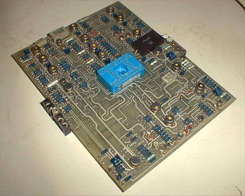
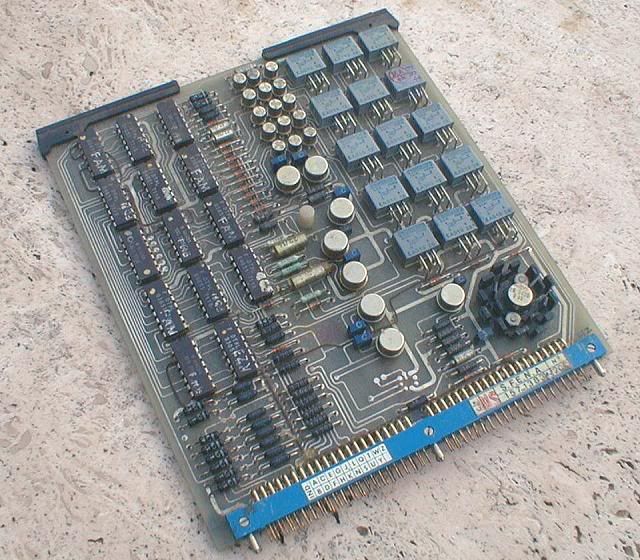
I have the rare privilege of actually having one of those rare "secret" air intake computers (AICU) sitting right next to my desk.
The circuit boards are mostly quite neat, with only the odd wire strap here and there.
However, the wiring of the unit itself, between the connectors, is a nightmare.
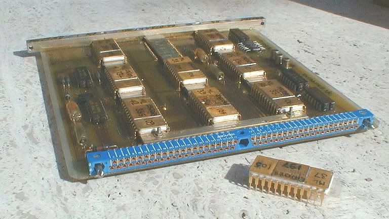
This is one of the PROM boards from the AICU, with one of the PROMs taken out of its socket. I have more photos, but will have to download those first, if anyone is interested.
Landroger
They're operational amplifiers, one per can!
Don't forget that all the computing in the AFCS computers was analog, not digital!
The vast majority were LM101As, with 741s in non-critical locations, and the odd LM108 for the really hiigh-precision stuff.
The board is actually a true antique, dating from one of the development aircraft.
We did not always do the kind of "butcher job" I described for the A/T. If there was enough time between major mods, the "firm" would redesign the board(s) and send us a new set, and the old ones would be binned... it made for better reliability. I kept a few as souvenirs.
I see you missed the real connector!
It's the big blue "thing" at the centre of the board, with no less than 80 pins.
This is the back of the card
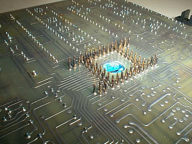
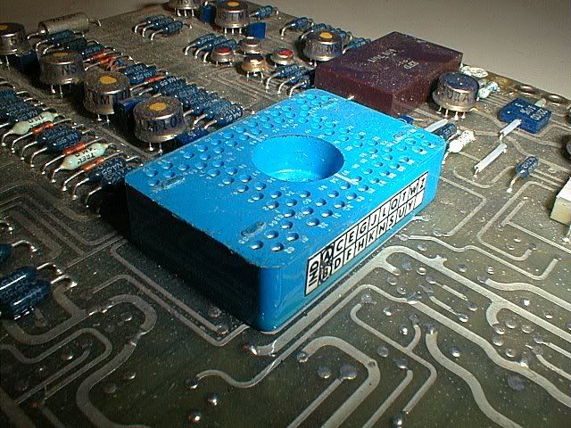
This is the central connector closer up
The idea wasn't bad at first sight.... it allowed stacking three boards on top of each other, so that many signals could pass from one board to another without any intermediate wiring. A small motherboard with a fourth conector would then take certain signals to other stacks, etc.
Another claimed advantage was that it made the board layout easier.
What was learned only gradually was that those connectors were hideously difficult to solder in place, and even more difficult to repair. Concorde was too far "on the way" to redesign the entire AFCS, so we learned to live with them, but the concept was abandoned afterwards.
The central connectors were only used for the analog boards ; the logic boards used more conventional 84-pin connectors on one side.
This is one of the logic boards.
Re the weight question, I would say M2dude's answer is a lot better than mine, so ignore my remarks.....
Re the wiring, Concorde had about 300km of it.
IIRC the A380 Flying Hippo, which is vastly bigger, "only" has about 500km of wiring, and it seems a lot of that is the IFE (in-flight entertainment)
CJ
I have the rare privilege of actually having one of those rare "secret" air intake computers (AICU) sitting right next to my desk.
The circuit boards are mostly quite neat, with only the odd wire strap here and there.
However, the wiring of the unit itself, between the connectors, is a nightmare.
This is one of the PROM boards from the AICU, with one of the PROMs taken out of its socket. I have more photos, but will have to download those first, if anyone is interested.
Landroger
What little horrors hid inside those TO5 cans?
Don't forget that all the computing in the AFCS computers was analog, not digital!
The vast majority were LM101As, with 741s in non-critical locations, and the odd LM108 for the really hiigh-precision stuff.
Apart from the fact that your board must be brand new - the track cutters and wire linkers hadn't got at it yet!
We did not always do the kind of "butcher job" I described for the A/T. If there was enough time between major mods, the "firm" would redesign the board(s) and send us a new set, and the old ones would be binned... it made for better reliability. I kept a few as souvenirs.
What is interesting are the connections - only eight pins, as far as I can tell? We had 15/25/60 pin 'D' connectors or multi path, gold 'edge' connectors at least
It's the big blue "thing" at the centre of the board, with no less than 80 pins.
This is the back of the card
This is the central connector closer up
The idea wasn't bad at first sight.... it allowed stacking three boards on top of each other, so that many signals could pass from one board to another without any intermediate wiring. A small motherboard with a fourth conector would then take certain signals to other stacks, etc.
Another claimed advantage was that it made the board layout easier.
What was learned only gradually was that those connectors were hideously difficult to solder in place, and even more difficult to repair. Concorde was too far "on the way" to redesign the entire AFCS, so we learned to live with them, but the concept was abandoned afterwards.
The central connectors were only used for the analog boards ; the logic boards used more conventional 84-pin connectors on one side.
This is one of the logic boards.
Re the weight question, I would say M2dude's answer is a lot better than mine, so ignore my remarks.....
Re the wiring, Concorde had about 300km of it.
IIRC the A380 Flying Hippo, which is vastly bigger, "only" has about 500km of wiring, and it seems a lot of that is the IFE (in-flight entertainment)
CJ
Join Date: Jan 2005
Location: France
Posts: 2,315
Likes: 0
Received 0 Likes
on
0 Posts
But you're right, nearly all of the mundane day-to-day design was with a slide rule, and pencil-and-paper.
I still remember how in about 1972 we had to start calculating the electric trim computer resistor values to 0.1% (rather than +-1%), so I bought my very first pocket calculator.... little red LED display, just the basic 4 functions. Cost �42, and those were 1972 pounds (what would the equivalent be today?). Luckily I could put it on my expense account ....
CJ
Join Date: Jan 2008
Location: FL 600. West of Mongolia
Posts: 463
Likes: 0
Received 0 Likes
on
0 Posts
Nick Thomas
You are right on the button first time, the white paint finish is for heat reflection purposes. (When I worked at Filton/Fairford I remember reading a document showing the difference in 'hot soak' supersonic skin temperatures for white and black paint finishes. I'm afraid I can't remember any figures (it was a couple of million years ago ) but there was quite a surprising difference.
G SXTY
A hearty welcome to this thread, and thank you for your very kind comments; I'm sure I speak for all the Concorde people here when I say that it is quite amazing that so many people, both aviation professionals as well as more 'normal' people are so fascinated by what most of us still regard as the finest aircraft ever to grace the skies. Your comment about 'men with slide rules' is so totally correct; I still remember the No7 & No8 design offices at Filton, these were huge rooms filled with draughtsmen's boards, a horde of designers, all without a single computer in sight.
Dave Rowland is a total gentleman as well as being an extremely knowledgeable flyer too, and I know he (like most of us) would be happy to talk about Concorde until the cows come home.
ChristiaanJ
Aghhhh The dreaded AICU. I'd almost forgotten the innards, as you say the motherboard wiring was a total nightmare (good piece of knitting I seem to remember). As far as the 'secret' bit of the AICU, I think we all know that is a little bit of Concorde mythology, more science museum than secret really. Around ten years ago we had some fairly substantial modifications done to the units, due to component obsolescence. (I seem to remember that some of the components concerned were not only out of production, but only a few hundred examples existed worldwide}. I do remember that the power supply board, resolver demodulator boards as well as a couple of others were replaced with new ones using modern components. The modification did do wonders for component reliability.
The PROM board that you have the photo of reminds me of a really amusing anecdote, told to me by Dr Ted Talbot a while ago. Now Ted is one of the true fathers of the Concorde air intake, an absolute genius as well as being a really pleasant gentleman indeed. I'm pleased to say that when I met him a few months ago, he was still as sharp as ever in his advancing years.
The story goes like this: Much of the Concorde intake development trials were flown out of Tangiers and Casablanca, where cold stratospheric temperatures would be guaranteed. Software changes as a result of the flight trials had to be done in there and 'the field'. The way that you made programmed the PROMS was by 'burning' each individual logic gate with a 9v battery. It was highly specialised, as well as extremely tedious work indeed, as we can all well imagine. Anyway, in while he was in Tangiers with aircraft G-AXDN, Ted had arranged for a rather lovely looking lady to be flown out to do his ROM programming. The HS 125 from Filton landed at Tangiers and taxied in and parked next to Concorde, and all the flight test people were waiting on the tarmac. The door of the 125 opened and out stepped this really leggy lady. 'who's the bint then ?' pipes up a really gritty airframe fitter, in a really broad Bristol accent. Without giving it a thought, Ted chirps 'she's come to blow my proms'. The little fitter grunts, glares at Ted and comes out with 'typical office staff, you get all the ***ing perks'.
Join Date: Mar 2007
Location: Cardiff UK
Age: 69
Posts: 118
Likes: 0
Received 0 Likes
on
0 Posts
Thanks M2dude and all other aviation professionals for making us "normal" posters so welcome on this thread.
Being a child of the sixties I clearly remember the feeling that we were at the dawn of a new technological age and Concorde and the Apollo project were the outstanding examples of what was possible. Great times.
Am not a computer expert but I have always wondered if the limitations of the 60's hardware meant that the software had to be more elegantly desgined than now?
Having watched the ITVV Concorde DVD, Captain David Rowlands and SEO Roger Bricknell come over as very knowlegable and friendly people. I hope they are both enjoying their retirement.
Thanks again
Nick
None but a blockhead
Join Date: Nov 1999
Location: London, UK
Posts: 535
Likes: 0
Received 0 Likes
on
0 Posts
Thanks from the peanut gallery seconded.
If anyone's looking for a good home for Concorde avionics, perhaps they might consider the National Museum of Computing at Bletchley Park, which has many fine examples of British electronics (LATCC donated an old ATC system) and is making a good fist of curating them.
I know the people there quite well, and would be delighted to put anyone in touch.
R
Join Date: May 2002
Location: UK
Posts: 140
Likes: 0
Received 0 Likes
on
0 Posts
A great thread and it only goes to show that you can always learn even about a subject that you thought you knew quite a lot about
As M2Dude described the rearwards transfer of fuel during acceleration was meant to be an automated process but in reality there was a lot of manual input. The first requirement of the F/E was to match the rearwards movement of the C of G to that of the ever increasing Mach number. If this was proving to be no problem he would take over the transfer manually by switching off the pumps on one side of tank 9 or 10 so as to pump only to either tank 5 or 7. This was because if you transferred evenly to these tanks due to their different shape size and position the aircraft would go out of trim laterally so the F/E would pump rearward just to one tank so as to keep the C of G going aft whilst maintaining lateral trim.
Being Concorde nothing was straight forward , which meant that when Tanks 5 and 7 ran out and you started using tanks 6 and 8, their size shape and position,was exactly opposite to that of tanks 5 and 7 so it now required the F/E to pump fuel the opposite way across the ship, using various valves and pumps, so as to keep the aircraft in trim laterally.
All the time he had to maintain the trim so as to keep an elevon trim of � deg down, which as fuel was burnt required him to trickle fuel forward from tank 11. On the longer trips such as those to and from BGI the fuel towards the end of cruise became quite low and to stop fuel in the collectors from dropping below 1000kgs each, fuel would be transferred from tank 11 into the collectors until the
C of G had reached it's forward limit at Mach 2.0 of 57.5 %. If then the collectors dropped to 1000kgs the aircraft had to descend to subsonic heights and speed.
Surges
Surges were not an uncommon or common event on Concorde,but when they happened as they usually affected both engines on that side the aircraft would lurch /yaw and everybody on board would know about it as �Her In Doors� would testify to that when glasses full and otherwise ended up in her lap during the meal service when a surge occurred.
The drill required all engines to be throttled to a predetermined position and the intake and engine control switches moved to their other position. If this stopped the surge then the throttles were restored to their cruise power a pair at a time and if no surge re-occured then the aircraft would return to cruise / climb
The crews post surge action was normally to have a cup of tea and light up a cigarette.
In the early days on a flight between London and Bahrain when the aircraft was in supersonic cruise the F/E who was a mature and refined gentleman, had to go to the toilet, which was just behind the front galley, and whilst there the engines surged. He was seen running from the toilet to the flight deck with his trousers around his ankles, which was a hell of shock to his refined nature
Enough for now sorry about the length
Join Date: Jan 2005
Location: France
Posts: 2,315
Likes: 0
Received 0 Likes
on
0 Posts
As far as the 'secret' bit of the AICU, I think we all know that is a little bit of Concorde mythology, more science museum than secret really.
The way I understood the story was that they tried to collect as many reasonably reliable spare AICUs for the last few delivery flights, so as not to have to suddenly cancel a flight.
The AICU was right at the top of the list of "unscheduled removals". IIRC the tea maker was second...
Around ten years ago we had some fairly substantial modifications done to the units, due to component obsolescence. (I seem to remember that some of the components concerned were not only out of production, but only a few hundred examples existed worldwide}. I do remember that the power supply board, resolver demodulator boards as well as a couple of others were replaced with new ones using modern components. The modification did do wonders for component reliability.
Much of the Concorde intake development trials were flown out of Tangiers and Casablanca, where cold stratospheric temperatures would be guaranteed.Software changes as a result of the flight trials had to be done in there and 'the field'. The way that you made programmed the PROMS was by 'burning' each individual logic gate with a 9v battery. It was highly specialised, as well as extremely tedious work indeed, as we can all well imagine.
"... 'burning' each individual logic gate with a 9v battery." I believe you, thousands wouldn't... Didn't you have at least some sort of programming unit?
I went through a similar exercise around 1976, but at that time at least we had a programming "suitcase", that let you copy the original in RAM, modifiy bit-by-bit with a keyboard, then 'burn' the PROM (or EPROM, by then) 'automatically'. Still took half the night....
Funny in a way how these things have stuck in our memories... But then, yes, Concorde was unique.
I've said this elsewhere, but I don't mind repeating it... in those days, there were two programmes to be part of. One was Apollo, the other was Concorde. And I've had the chance to be part of one of them.
CJ
CJ
Quite right on the two projects of the Sixties. Many of the engineers on Apollo were ex-Avro Arrow types. The shame is that these projects could not get off the ground (no pun intended) today, even with modern technology. Just a "relofted" (to use a nautical term) Concorde would be a marvelous machine. Politics, environmental regs and NIMBYism would kill anything like it.
I was speaking with a seat mate on an airliner who happened to be a civil engineer. As a young man, he had worked on the US Interstate Highway system, said it could never be done today and widening and improving the one that exists is very hard to approve.
Mach2dude
How was takeoff performance calculated? Was it very different from subsonic jets and how did Vzf fit in?
GF