


Concorde question

Join Date: Jul 2002
Location: UK
Posts: 3,093
Likes: 0
Received 0 Likes
on
0 Posts

Join Date: Feb 2009
Location: Jungles of SW London
Age: 77
Posts: 354
Likes: 0
Received 0 Likes
on
0 Posts
Vortex lift.
Okay, for the benefit of all the SLF and Vulgar Curiosity Seekers watching this thread, I will ask the 'nice but dim' question. 
I thought I knew a bit about aeroplanes, but M2Dude, CJ and now Clive are pushing my knowledge and understanding to their limits. I see them on Clive's two fabulous images and I've heard some of the pilots - Exwok and Bellerophon - talk of it, but up to now it was something I could take for granted and move on. Now I have to come clean and ask. Vortex lift for dummies please gentlemen?
The end on view is very dramatic and I can only surmise the rotor of air above the wing somehow accelerates it to reduce its density still further, thus generating lift. More lift indeed than the cord profile can provide without creating too much drag. Close? Or wooden spoon for Rog?
Roger.
Join Date: Jan 2005
Location: France
Posts: 2,315
Likes: 0
Received 0 Likes
on
0 Posts
In my case, it's easier... I've become bitten by the Concorde bug again over the last ten years or so, and pulled dozens of similar diagrams from the documentation to refresh my memory.
Certainly it sounds, from time to time, that there were a million little black boxes dotted all over her airframe.
I suspect however, that many of the 'terms' and 'laws' spoken about are simply a gate or two, perhaps an op' amp, placed in a larger circuit that modulates the output of that board, thus creating the law or term.
Op-amps also were used for other functions such as demodulators (converting AC signals to DC) or comparators and level detectors.
I still mean to write some posts on "how to compute without a digital computer", but it'll have to wait until after the holidays.
Digital control is a hell of a lot easier than Analogue - in my humble opinion. 
In the 'olden' days we'd draw block diagrams like the one for the SFC, and once we agreed about all the functions we wanted, we just drew the schematics for each of the functions.
No sequencing, no real-time clock, no A/D or D/A conversion, no worries about cycle time or memory allocation. No programming-language issues, no naming of variables, no compiler faults, no software to debug.
You should try it sometime......
The major issue was, of course, that you ended up with a lot more hardware for the same functionalities, hence more weight, and more power consumption.
And the other issue, already alluded to in earlier posts, is that analogue computing is inherently not highly accurate.
In many cases of system control, a percent or two of precision is perfectly acceptable. But if a far higher precision is needed, like for instance in the intertial navigation system, or the core computing for the air intakes, only digital computing can do the job.
Seasons greetings to everyone on this thread from me too.
Christian
Join Date: Jan 2008
Location: FL 600. West of Mongolia
Posts: 463
Likes: 0
Received 0 Likes
on
0 Posts
ChristiaanJ
Yippeeeee we have a winner. Coffin Dodgers photo of my poor old G-BOAA shows the stiffeners perfectly.  (I was starting to think that I had gone even more bonkers than usual, and was imagining the things
  ).
).
Best regards to all
Dude
M2dude will have to confirm that the 'lateral stiffeners' he is thinking of are indeed the very roughly 2' long and 5" strips at the location of each spar just outboard of the engine, that are very clearly visible on Coffin Dodger's photo of 'AA.
(I was starting to think that I had gone even more bonkers than usual, and was imagining the things ).Best regards to all
Dude
Join Date: Feb 2009
Location: Jungles of SW London
Age: 77
Posts: 354
Likes: 0
Received 0 Likes
on
0 Posts
ChristiaanJ
Thank you CJ, this too adds texture to bare fact.
This will be interesting, I shall look forward to that.
I'll admit I was still a bit doubtful, until you wrote this, particularly:-
and I say Amen to that! Modern software, at least the stuff that drives my kit, comes delivered with bugs and very often the 'workaround list', until that is superseded by an even longer list. 
The software on the original EMIScanners was written in BASIC and was amazingly efficient as well as being surprisingly bug free and 'bomb proof'. Of course it wasn't very quick and it was possible to figure out almost exactly what was happening at any given millisecond.
Modern software - on our kit anyway - is doing fifteen things at once while processing huge dollops of data - much of it computational - and no-one, not even the software writers, can tell you anything more than approximately what is happening at any time.
I think, perhaps, my respect for the analogue designers comes from my relative weakness on the core electronics. I've been a 'System Engineer' for too long and some days I never even get a screwdriver out.
Looking forward to more guys.
Roger.
I still mean to write some posts on "how to compute without a digital computer", but it'll have to wait until after the holidays.
No sequencing, no real-time clock, no A/D or D/A conversion, no worries about cycle time or memory allocation. No programming-language issues, no naming of variables, no compiler faults, no software to debug.
no compiler faults, no software to debug.
Modern software, at least the stuff that drives my kit, comes delivered with bugs and very often the 'workaround list', until that is superseded by an even longer list. The software on the original EMIScanners was written in BASIC and was amazingly efficient as well as being surprisingly bug free and 'bomb proof'. Of course it wasn't very quick and it was possible to figure out almost exactly what was happening at any given millisecond.
Modern software - on our kit anyway - is doing fifteen things at once while processing huge dollops of data - much of it computational - and no-one, not even the software writers, can tell you anything more than approximately what is happening at any time.
I think, perhaps, my respect for the analogue designers comes from my relative weakness on the core electronics. I've been a 'System Engineer' for too long and some days I never even get a screwdriver out.
Looking forward to more guys.
Roger.
Join Date: Jan 2008
Location: Bracknell, Berks, UK
Age: 52
Posts: 1,133
Likes: 0
Received 0 Likes
on
0 Posts
Here's a new question for you...
We all know Concorde went at Mach 2 at FL600, but were there instances (for the press, certification, etc) that you went supersonic considerably closer to the deck? and what issues (if any) did that bring up?
We all know Concorde went at Mach 2 at FL600, but were there instances (for the press, certification, etc) that you went supersonic considerably closer to the deck? and what issues (if any) did that bring up?
Join Date: Jan 2005
Location: France
Posts: 2,315
Likes: 0
Received 0 Likes
on
0 Posts
Flight envelope
Those are the official certified limits.
I doubt somehow anybody went beyond those "for the press".....
But during certification, yes, each of those limits was exceeded, slowly and carefully, to be able to draw those official operational limits on the document.
For instance, the certified Mmo is 2.04. During certification, G-BBDG (202) went to Mach 2.21....
Even while staying within the limits, she could could exceed Mach 1 just below 30,000 ft.
Also, during the acceptance flights after major overhauls, most of those envelope limits would be exceeded by a given margin, to prove the aircraft still met all the certification requirements. Whether any of that was done 'closer to the deck', I wouldn't know.
The 'issues' would vary. Performance would be one issue... Delta Golf (and 01, who went to Mach 2.23) basically "ran out of steam" at that speed.
Another issue would be that 'going beyond the borders' shortened the fatigue life of the airframe, and it was difficult to assess exactly by how much. It was one of the reasons why Delta Golf and Sierra Bravo (the certification aircraft) in the end never went into service.
CJ
Join Date: Dec 2010
Location: Europe
Age: 88
Posts: 290
Likes: 0
Received 0 Likes
on
0 Posts
We all know Concorde went at Mach 2 at FL600, but were there instances (for the press, certification, etc) that you went supersonic considerably closer to the deck? and what issues (if any) did that bring up?
Generally speaking the region from say 0.98 to 1.2M is one to pass through and be thankful!
CliveL
Join Date: Dec 2010
Location: Europe
Age: 88
Posts: 290
Likes: 0
Received 0 Likes
on
0 Posts
OK Vortex Lift for Dummies!
Lets start with a comparison of the lft on a conventional subsonic wing with that of a slender wing like Concorde:
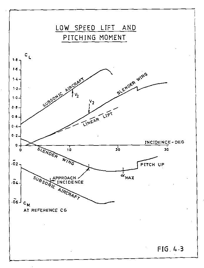
The subsonic line is linear, the slope depends on the geometry of the wing; high aspect ratio wings have a higher slope than low aspect ratio, unswept wings a higher slope than swept. Concorde, being a low aspect ratio swept wing has no chance!
To get a decent approach speed with a delta wing which has 'conventional' wing sections you need either a long U/C and work with high landing AoA or a large wing area to get the wing loading down. I would put the Avro Vulcan in the latter class. A large wing area is bad news for supersonic aircraft, but the Germans, working during WW2 found that if you give the delta sharp leading edges the flow separates at the leading edge and forms a pair of vortices that flow over the upper wing surface.
A vortex, if you could see it, is like a tornado (twister) turned on its side. The essential feature is that it is associated with low static pressures. As you get closer to the centre of the vortex the pressure drops more and more. The red zones at the centre of that transverse view are very low pressure indeed, but even the outer zones have quite low pressure.
I will have to put it up as a separate posting, but there are pictures that show that as AoA increases not only does the vortex get stronger (more suction) but the area of the wing affected by the vortex also inceases. This 'double whammy' gives the vortex a nonlinear effect. This 'nonlinear' lift is what is sometimes called 'vortex lift'.
It doesn't come for nothing - since by definition the flow is separated from the leading edge there is no alleviating 'leading edge suction' to reduce drag, and you won't go very far wrong if you take the drag of an aircraft with such a wing as Profile Drag plus Lift (times) tan AoA.
Concorde is a bit more subtle - the nose of the wing is drooped so that the flow does not separate until the AoA reaches 6 or 7 deg, giving us a good L/D in subsonic cruise whilst still having a healthy lift at approach speed.
Does this fit the bill?
CliveL
Lets start with a comparison of the lft on a conventional subsonic wing with that of a slender wing like Concorde:
The subsonic line is linear, the slope depends on the geometry of the wing; high aspect ratio wings have a higher slope than low aspect ratio, unswept wings a higher slope than swept. Concorde, being a low aspect ratio swept wing has no chance!
To get a decent approach speed with a delta wing which has 'conventional' wing sections you need either a long U/C and work with high landing AoA or a large wing area to get the wing loading down. I would put the Avro Vulcan in the latter class. A large wing area is bad news for supersonic aircraft, but the Germans, working during WW2 found that if you give the delta sharp leading edges the flow separates at the leading edge and forms a pair of vortices that flow over the upper wing surface.
A vortex, if you could see it, is like a tornado (twister) turned on its side. The essential feature is that it is associated with low static pressures. As you get closer to the centre of the vortex the pressure drops more and more. The red zones at the centre of that transverse view are very low pressure indeed, but even the outer zones have quite low pressure.
I will have to put it up as a separate posting, but there are pictures that show that as AoA increases not only does the vortex get stronger (more suction) but the area of the wing affected by the vortex also inceases. This 'double whammy' gives the vortex a nonlinear effect. This 'nonlinear' lift is what is sometimes called 'vortex lift'.
It doesn't come for nothing - since by definition the flow is separated from the leading edge there is no alleviating 'leading edge suction' to reduce drag, and you won't go very far wrong if you take the drag of an aircraft with such a wing as Profile Drag plus Lift (times) tan AoA.
Concorde is a bit more subtle - the nose of the wing is drooped so that the flow does not separate until the AoA reaches 6 or 7 deg, giving us a good L/D in subsonic cruise whilst still having a healthy lift at approach speed.
Does this fit the bill?
CliveL
Join Date: Dec 2010
Location: Europe
Age: 88
Posts: 290
Likes: 0
Received 0 Likes
on
0 Posts
 Ok, second picture (can anyone tell me how to attach more than one?)
These need a bit of explaining I'm afraid. They are 'oil flow' pictures - you paint the model wing with a mixture of paraffin, engine oil and lamp black and blow air over it. The resulting pattern shows how the air is flowing (or not flowing, which is its primary purpose) over the wing surface.
I the diagram marked up in red the 'S' shaped line is a typical streamline where the air is brought down onto the surface inboard, moves downstream and across towards the tip under the combined action of fore and aft velocity and vortex rotational velocity and tis finally lifted off the surface by the vortex. the triangular zone marked out in red is the area of the wing 'scrubbed' by the vortex flow. If you compare the pictures at various AoA you will see that this area increases substantially as AoA increases.
On the21 deg picture you can also see signs of a second vortex between the main vortex and the wingtip, but this is not the classic 'tip vortex'
CliveL
Join Date: Jan 2004
Location: Norfolk UK
Age: 88
Posts: 27
Likes: 0
Received 0 Likes
on
0 Posts
Vortex Lift
Clive,
Thanks for the diagrams about vortex lift.
I seem to remember, as a flight test engineer having the good fortune to sit in on a fair number of landings during Concorde 'DG development and certification flying, that you could feel the onset of vortex lift from a very light vibration through the airframe, during the slowing down to approach speeds. I think it was more noticeable sitting back at the FTE seats at the instrumentation area in the cabin rather than on the 4th seat on the flight deck. I cannot remember if that was close to the 7 degree onset alpha or something closer to the approach alpha. Has anyone else commented on this?
Andrew
Join Date: Sep 2007
Location: UK
Age: 58
Posts: 128
Likes: 0
Received 0 Likes
on
0 Posts
It could be felt on the flight deck, although the onset was not particularly noticeable, and tended to be masked by the fact that one generally lowered the visor and dropped the nose to 5 degs at about the same time.
Join Date: Jan 2005
Location: France
Posts: 2,315
Likes: 0
Received 0 Likes
on
0 Posts
Somewhere on these 50+ pages there is a mention of a narrow "to-be-avoided" speed band (buffet) which sounds as if referred to the same phenomenon, but I haven't been able to find it again.
Maybe the original poster remembers and can point us back?
CJ
Maybe the original poster remembers and can point us back?
CJ
Join Date: Dec 2010
Location: Europe
Age: 88
Posts: 290
Likes: 0
Received 0 Likes
on
0 Posts
I cannot remember if that was close to the 7 degree onset alpha or something closer to the approach alpha. Has anyone else commented on this?
CliveL
Join Date: Jan 2005
Location: France
Posts: 2,315
Likes: 0
Received 0 Likes
on
0 Posts
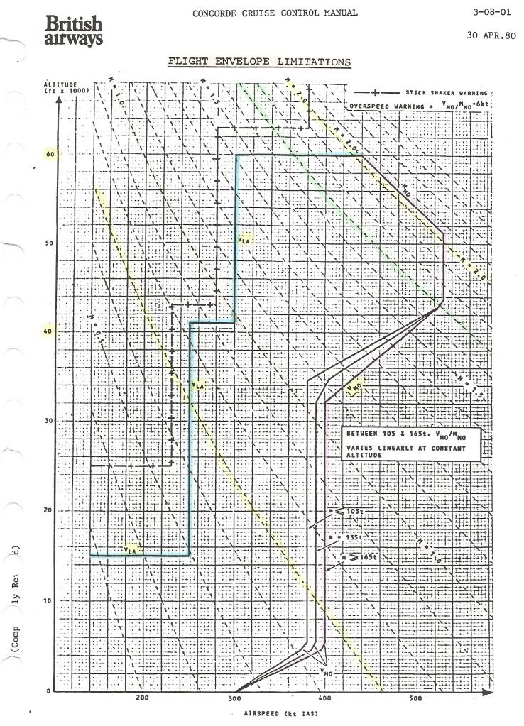
For convenience, I repeat Bellerophon's diagram of the flight envelope here.
Mike's earlier question had me scratching my head too, hence my question.
What are the fundamental reasons for each of the limitations, and what were the consequences of going outside them?
Going clockwise from the left, we have :
VLA (lowest admissible speed)
One would expect a curve for constant alpha max against IAS and altitude, not the staircase in the diagram.
Was this for simplicity of use of the diagram?
Max altitude (60,000ft)
This is the 'simplest' one: it was the highest 'safe' altitude from which an emergency descent could be made, in the case of a window blowing out, without having the blood of the pax boil....
Test flights (without pax, and with the crew pressure-breathing oxygen) did go as high as 69,000ft.
Mmo (max operating Mach number)
Mach 2.04 is usually quoted as having been chosen to assure an adequate life of the airframe.
But what effect does a higher Mach number as such have?
Or are Mmo and Tmo (127�C) directly related?
Vmo (max operating speed) = 530kts until 43,000ft
I suppose this is related to structural limits (qmax)?
Vmo reducing to 380/400kts at about 33,000ft
What is the limiting factor here (other than qmax)?
Vmo constant at 380/400kts down to 5,000ft
What is the limiting factor here? The answer will no doubt also explain why this is slightly weight-dependent.
Vmo reducing to 300kts between 5,000ft and 0 ft
Why the sudden change below 5,000ft?
CJ
Join Date: Feb 2009
Location: Jungles of SW London
Age: 77
Posts: 354
Likes: 0
Received 0 Likes
on
0 Posts
Vortex Lift.
Does this fit the bill?
CliveL
CliveL
As the AoA increases when Concorde slows down, the vortex comes into being and becomes stronger as the angle increases, creating a low pressure tube into which the wing is 'sucked upwards' - vis vortex lift. How did I do?

These need a bit of explaining I'm afraid. They are 'oil flow' pictures - you paint the model wing with a mixture of paraffin, engine oil and lamp black and blow air over it. The resulting pattern shows how the air is flowing (or not flowing, which is its primary purpose) over the wing surface.
Thanks for the explanation - it was less painful than I had feared.
Roger.
Join Date: Jan 2005
Location: France
Posts: 2,315
Likes: 0
Received 0 Likes
on
0 Posts
CAAAD,
LOL.....
If so, same question.
Can you explain the boundaries of the Olympus Relight Envelope?
Cheers,
CJ
PS : If you have a graph for that, it would be most gratefully received here, I'm sure!
LOL.....
If so, same question.
Can you explain the boundaries of the Olympus Relight Envelope?
Cheers,
CJ
PS : If you have a graph for that, it would be most gratefully received here, I'm sure!
Last edited by ChristiaanJ; 26th Dec 2010 at 17:07. Reason: Added 'PS'
Join Date: Dec 2010
Location: Europe
Age: 88
Posts: 290
Likes: 0
Received 0 Likes
on
0 Posts
[quote=ChristiaanJ]VLA (lowest admissible speed)
One would expect a curve for constant alpha max against IAS and altitude, not the staircase in the diagram.
Was this for simplicity of use of the diagram?[quote]
I don't have a complete explanation for all the regions - it was a long time ago and I'll need to dig, but:
Below 16000 ft Vla obviously needs to go as low as Vref to cover landing at elevated airfield altitudes. At present I don't have a satisfactory explanation for 250 kts between 16000 ft and about 45000 ft (250kts/Mach 1.0) A constant value in IAS is what you would get for a constant CLmax (the alphamax is not really the driver). Vla should give a margin above stall, and a quick sum suggests that 250 kts would be consistent with a 1.3Vs condition and a CLmax of about 0.8 up to Mach 1.0, which is not unreasonable, but I am not saying that is the correct interpretation.
From 45000 ft to 60,000 ft I think Vla may be set by manoeuvre requirements. Certainly the forward CG envelope boundary between 1.0M and 1.5M discussed in earlier posts is very close to the requirement to be able to pull 1.2g with half hinge moment available at Vla and heavy weights. Again not certain, but best guess at the moment.
Yes
[quote]Mmo (max operating Mach number)
Mach 2.04 is usually quoted as having been chosen to assure an adequate life of the airframe.
But what effect does a higher Mach number as such have?
Or are Mmo and Tmo (127�C) directly related?[quote]
I have always been puzzled by this statement as one does not normally associate Mach Number with a life limit. Going through my collection of lectures I found another, more plausible explanation:
quote" The scheduled cruise mach Number was 2.0. associated with a structural total temperature of 400 degK. Above ISA +5 Mc was cut back to maintain 400 degK.
To cope with variations of flight mach Number about Mc associated with often rapid and significant changes in wind and temperature which occur particularly in the vicinity of the tropopause (which can of course be as high as 60,000 ft in the tropics) a maximum operating Mach Number (Mmo) of 2.04 is selected" unquote [Leynaert, Collard and Brown, AGARD Flight Mechanics Symposium October 1983]
This is much more in line with my memory on this subject.
Yes in principle, but it is a bit chicken and egg, since 530 kts also represents a very good choice for best performance, and I am sure that the stucture would have been built to cope if a higher speed was needed for performance reasons. To the best of my knowledge there is no structural design case that would be critical in this flight regime (other than flutter of course)
Same as earlier - transonic manoeuvre requirements with failed hydraulics, matched to aircraft weight and CG envelope possibilities.
Same again.
I'm not entirely sure, but:
a) there is absolutely no advantage is having a high Vmo at low altitudes as it could not be exploited even if one wanted to because of ATC limitations to 250 kts below 10,000 ft (in the USA at least)
b) there are a lot of things that get rapidly worse if you encounter them at high speed and which are anyway more likely at low altitude - hail, birds etc.
So why store up trouble for yourself!
CliveL
One would expect a curve for constant alpha max against IAS and altitude, not the staircase in the diagram.
Was this for simplicity of use of the diagram?[quote]
I don't have a complete explanation for all the regions - it was a long time ago and I'll need to dig, but:
Below 16000 ft Vla obviously needs to go as low as Vref to cover landing at elevated airfield altitudes. At present I don't have a satisfactory explanation for 250 kts between 16000 ft and about 45000 ft (250kts/Mach 1.0) A constant value in IAS is what you would get for a constant CLmax (the alphamax is not really the driver). Vla should give a margin above stall, and a quick sum suggests that 250 kts would be consistent with a 1.3Vs condition and a CLmax of about 0.8 up to Mach 1.0, which is not unreasonable, but I am not saying that is the correct interpretation.
From 45000 ft to 60,000 ft I think Vla may be set by manoeuvre requirements. Certainly the forward CG envelope boundary between 1.0M and 1.5M discussed in earlier posts is very close to the requirement to be able to pull 1.2g with half hinge moment available at Vla and heavy weights. Again not certain, but best guess at the moment.
Max altitude (60,000ft)
This is the 'simplest' one: it was the highest 'safe' altitude from which an emergency descent could be made, in the case of a window blowing out, without having the blood of the pax boil....
Test flights (without pax, and with the crew pressure-breathing oxygen) did go as high as 69,000ft.
This is the 'simplest' one: it was the highest 'safe' altitude from which an emergency descent could be made, in the case of a window blowing out, without having the blood of the pax boil....
Test flights (without pax, and with the crew pressure-breathing oxygen) did go as high as 69,000ft.
[quote]Mmo (max operating Mach number)
Mach 2.04 is usually quoted as having been chosen to assure an adequate life of the airframe.
But what effect does a higher Mach number as such have?
Or are Mmo and Tmo (127�C) directly related?[quote]
I have always been puzzled by this statement as one does not normally associate Mach Number with a life limit. Going through my collection of lectures I found another, more plausible explanation:
quote" The scheduled cruise mach Number was 2.0. associated with a structural total temperature of 400 degK. Above ISA +5 Mc was cut back to maintain 400 degK.
To cope with variations of flight mach Number about Mc associated with often rapid and significant changes in wind and temperature which occur particularly in the vicinity of the tropopause (which can of course be as high as 60,000 ft in the tropics) a maximum operating Mach Number (Mmo) of 2.04 is selected" unquote [Leynaert, Collard and Brown, AGARD Flight Mechanics Symposium October 1983]
This is much more in line with my memory on this subject.
Vmo (max operating speed) = 530kts until 43,000ft
I suppose this is related to structural limits (qmax)?
I suppose this is related to structural limits (qmax)?
Vmo reducing to 380/400kts at about 33,000ft
What is the limiting factor here (other than qmax)?
What is the limiting factor here (other than qmax)?
Vmo constant at 380/400kts down to 5,000ft
What is the limiting factor here? The answer will no doubt also explain why this is slightly weight-dependent.
What is the limiting factor here? The answer will no doubt also explain why this is slightly weight-dependent.
Vmo reducing to 300kts between 5,000ft and 0 ft
Why the sudden change below 5,000ft?
Why the sudden change below 5,000ft?
a) there is absolutely no advantage is having a high Vmo at low altitudes as it could not be exploited even if one wanted to because of ATC limitations to 250 kts below 10,000 ft (in the USA at least)
b) there are a lot of things that get rapidly worse if you encounter them at high speed and which are anyway more likely at low altitude - hail, birds etc.
So why store up trouble for yourself!
CliveL