


AF 447 Search to resume

Join Date: Apr 2010
Location: Lower Silesia
Age: 77
Posts: 28
Likes: 0
Received 0 Likes
on
0 Posts
Bearing in mind the limited width of the ITCZ in the area of AF447's demise, and given the considerable range (air to air) for a high altitude loitering Zephyr drone, it should be possible to keep the drone out of any nasty weather's harm's way (see below). For polar duty, the "out of season" lack of insolation could well be a downing discrepancy for any solar-powered winged beastie. So for high latitude on station polar radio-relay duties, a helium-filled solar-powered (and -thrusted) blimp may prove to be a better solution. This one see link is capable of months on blimp-station at 60,000ft. Its solar panels can be on its sides.
.
The ITCZ is a region of light winds, which lends it the name the doldrums. The convergence of the Southeast and Northeast Trade Winds, within the doldrums, creates a zone of Cumulus clouds and attendant shower activity. Cumulus clouds often build up to great heights. Aircraft reports have estimated tops of Cumulonimbus to be as high as 12,000 m. The ITCZ varies from 20 miles to as much as 300 miles in width, and typically has an undulating conformation.
.
Seasonal Meandering of the ITCZ. We are interested in the ITCZ because, under certain circumstances, tropical depressions on the ITCZ intensify to hurricanes. It may seem puzzling that the ITCZ can produce cyclones, when the Coriolis force is at its weakest near the equator. The answer to this puzzle lies in the fact that the ITCZ is not stationary on the equator, but migrates north and south with the seasons. The ITCZ moves north during the high-sun season of the Northern Hemisphere, and south during the high-sun season in the Southern Hemisphere. These movements are not perfectly symmetrical above and below the equator, because of the influence of land masses, among other factors.

.
from this link
.
The ITCZ is a region of light winds, which lends it the name the doldrums. The convergence of the Southeast and Northeast Trade Winds, within the doldrums, creates a zone of Cumulus clouds and attendant shower activity. Cumulus clouds often build up to great heights. Aircraft reports have estimated tops of Cumulonimbus to be as high as 12,000 m. The ITCZ varies from 20 miles to as much as 300 miles in width, and typically has an undulating conformation.
.
Seasonal Meandering of the ITCZ. We are interested in the ITCZ because, under certain circumstances, tropical depressions on the ITCZ intensify to hurricanes. It may seem puzzling that the ITCZ can produce cyclones, when the Coriolis force is at its weakest near the equator. The answer to this puzzle lies in the fact that the ITCZ is not stationary on the equator, but migrates north and south with the seasons. The ITCZ moves north during the high-sun season of the Northern Hemisphere, and south during the high-sun season in the Southern Hemisphere. These movements are not perfectly symmetrical above and below the equator, because of the influence of land masses, among other factors.
.
from this link

Join Date: Apr 2010
Location: Lower Silesia
Age: 77
Posts: 28
Likes: 0
Received 0 Likes
on
0 Posts
Everybody talking at once......avoiding that annoying superheterodyne squeal
Murphywasright addressed the problem of mutual interference if aircraft were to be broadcasting their data on the one V/UHF frequency. This has been resolved within "link" technology. i.e. no mutual interference. I imagine that it utilizes the same (or basically similar) handshaking protocols used to avoid interference/data collisions on the internet's pipes.
TADIL-A/Link 11 is a secure half-duplex TADIL radio link used by NATO that receives or transmits--but not both simultaneously--a sequential data exchange digital link. It exchanges digital information among multiple airborne, land-based, and ship-board data systems. It is the primary means for exchange of complex changing data such as radar-tracking information beyond line of sight. TADIL-A can be used on either high frequency (HF) or ultrahigh frequency (UHF). However, the U.S. Army uses only HF.
Link 11 will be replaced by Link 22.
Link 11 will be replaced by Link 22.
Join Date: Jun 2009
Location: NNW of Antipodes
Age: 81
Posts: 1,330
Received 0 Likes
on
0 Posts
Bearfoil wrote in Post #1831
That ACARS was successful (and disseminated), is a case in point. Simply because the data encapsulated in the company channel speaks to a possibility of capturing accident information, that would seem to be a starting point.
That ACARS was successful (and disseminated), is a case in point. Simply because the data encapsulated in the company channel speaks to a possibility of capturing accident information, that would seem to be a starting point.
Basic GPS data including position and altitude sent every 10 seconds with the remaining unused period in each 10 second interval used for selected flight parameters would be of use. It should be remembered that the position data is already being broadcast (by most aircraft) on ADS-B, and if means can be found for receiving and recording that data, then the ACARS channels flight data upload can be increased proportionately.
I am not against the promotion of various alternate means to get all or some of this information from flights over oceanic areas, but I am mindful of the BEA's Flight Data Recovery Working Group, and the expertise they accumulated for that project. Change happens slowly, especially when the infrastructure doesn't exist, or where industry standards/protocols need to be changed and approved by statutory authorities.
mm43
Guest
Posts: n/a
Hello mm43.
In emergencies, things need to get simple. I agree with you of course that change can be glacial in the industry.
Nothing focuses one's attention more than execution at dawn. It is tempting to rely far too much on ACARS in this specific accident. It was rather a fluke the data was made public. Without it, the several searches would have been even more broad and haphazard.
A more intensive data link triggered on Pilot/A/C thresholds could of course be route specific, the equipment made modular, and training would be somewhat straightforward. It is too much to ask, even with a fully cooperative roster of players.
Beyond this is the capability of displaying absolutely essential flight data to the cockpit as well. No offense intended.
bear
Join Date: Jun 2009
Location: I am where I am and that's all where I am.
Posts: 660
Likes: 0
Received 0 Likes
on
0 Posts
Weewinkywilly, there are some nice HF transmission tools that chiefly work via NVIS, Near Vertical Incidence Skywave. This depends on common properties of the ionosphere over the HF spectrum. It can be reduced to virtually a telephone technology using ALE, Automatic Link Establishment. It is claimed the military squeezes as much as ISDN level bandwidths out of HF, 128kbps. Link establishment time is small. And for data transmissions of low data rate aircraft information these might do well.
Again, two problems exist, frequency allocations and polar regions.
Frequency allocations can be squeezed out, perhaps. While HF broadcasting is in severe decline squeezing out more bands for amateur radio has proven very difficult. Were these inactive or no longer needed HF broadcasting frequencies no longer needed obtaining new ham bands should, logically, be easy. So I suspect this will be a serious problem even for aircraft safety issues. A lot of frequencies will be needed and significant weight additions for the new transceivers, antennas, and computers will exist. These can all be dealt with.
Polar regions remain the tough spot. I am not well versed in the ionosphere's configuration at the magnetic poles. I'm not sure it has been studied. It WILL be vastly different due to the interactions with the Earth's magnetic fields. And we have auroras in the polar regions. Auroras shred and spread signals. Most transmissions, AM, FM, or CW sound more like they've been fed through something for audio like shredding is to junk credit card offers. SSB works, in so far as it is "understandable", amazingly so compared to CW. AM and FM are generally unintelligible unless the power is very high. Since SSB can get through that suggests that somehow data should be able to get through at about the bit rate for vocoded speech, 100 to 200 bps, using brute force techniques. Maybe an off the shelf technology to deal with it exists. I'd expect it still would be classified if it does. How many wars do we fight in the polar regions?
Maybe this can be done. But the proposal needs more polish performed by people with more current experience with recently unclassified systems than I have at this moment.
Guest
Posts: n/a
From the NTSB/Rudder thread, a question for 330 pilots. RTLU fail/prior limit is reported as 7.9degrees, full sweep, by inspection. The Limit in a/s> 272knots is the last one before Law switch, but even at 4degrees each direction, with no modulation of rate of deflection, and a fully powered Rudder, what is the effect of rapid cycling of Rudder: at m.82, at m.82 with a stop @4degrees, and with a 7.9 degree deflection (stop to stop) ? Under what conditions would the Rudder be used at that velocity?
JD-EE, For purposes of this discussion, and a proposed fit of enhanced Comm over areas of low likelihood of FDR/CVR recovery, wouldn't ice be considered a similar deck as land?
JD-EE, For purposes of this discussion, and a proposed fit of enhanced Comm over areas of low likelihood of FDR/CVR recovery, wouldn't ice be considered a similar deck as land?
Join Date: Jun 2009
Location: NNW of Antipodes
Age: 81
Posts: 1,330
Received 0 Likes
on
0 Posts
Bearfoil wrote:-
RTLU fail/prior limit is reported as 7.9degrees, full sweep, by inspection.
RTLU fail/prior limit is reported as 7.9degrees, full sweep, by inspection.

The best description on the design criteria and in service use I have seen can be found at:-
http://pilotlab.net/aircraft-manufacture/airbus/rudder-loads.pdf
mm43
Last edited by mm43; 9th Aug 2010 at 23:48.
Guest
Posts: n/a
mm43
Thank you for the link, it is most helpful. Help me with some nomenclature if you would. My reading of both the second report and the initial one tells me that "Rudder Angle" (a singular) to me has historically meant the angle between the longitudinal line of the Fuselage and the angle described by the Rudder face.relative to same. Sweep describes the arc between stops (or input, as the case may be. They are two different things. The Graph likewise shows a ~4degree angle consistent with RTLU default after Law Change for the assumed speed, 272 knots. Since the angle available on each side is certainly not necessarily utilized, the descriptor it seems to me would relate to a single condition, (deflection) independent of (though certainly made possible by) the restriction (Mechanical stops). Here to learn.
bear
Join Date: May 2010
Location: Le Shed on the Tropic of Capricorn
Age: 62
Posts: 22
Likes: 0
Received 0 Likes
on
0 Posts
Rudder travel
Doesn't the A332 have a larger VS than the A333? (due to the -200 being shorter ie to provide the same stabilising moment). Is the rudder the same between the -200 and the -300, with the same deflection limits? or is the rudder larger on the -200 with different deflection limits?
thanks
Ian
thanks
Ian
Join Date: Jun 2009
Location: NNW of Antipodes
Age: 81
Posts: 1,330
Received 0 Likes
on
0 Posts
Bearfoil
I'll get back to you on the substance of your question, but I think you should have a look at the FCOM for the A330. You can download it, or just view it at:-
A330 - Flight Controls
FluidFlow
I haven't got the precise dimensions of the V/S for the A333 series, but am aware that the height of the A332 V/S is about 55cm greater than the A333. The rudder limits are the same, and I am assuming that the rudder area has been varied to match the different V/S designs.
mm43
Last edited by mm43; 11th Aug 2010 at 08:50. Reason: changed 50cm for 55cm
Guest
Posts: n/a
Thanks, I look forward to your reply. Meantime, and without the "Bird", a pilot has no heading (crab) reference, and if Rudder is used to return 447 to "En Ligne de Vol," he has a critical need to know the response his control input has had. Should he stop too soon, or too late, the Rudder gets rapidly out of sync with the Fuselage direction, and each subsequent Rudder input puts the machine more out of whack, until shock loads rip off the VS. This assumes that the Rudder has mechanical stops, but no rated deployment; the Rudder slams to its stop each time he applies any Rudder at all..And below 272 knots, as 587 shows, the engines are scraped off.
Join Date: Jun 2009
Location: I am where I am and that's all where I am.
Posts: 660
Likes: 0
Received 0 Likes
on
0 Posts
Bearfoil, "JD-EE, For purposes of this discussion, and a proposed fit of enhanced Comm over areas of low likelihood of FDR/CVR recovery, wouldn't ice be considered a similar deck as land?"
Ice is going to be very pure water, which is an insulator. It will have a different dielectric constant. So there will be some reflection. It also is not a very good insulator so there will be dissipation. I do know that you can speak by radio, sometimes. from Antarctica to the US on amateur radio. But that's using techniques for low angle radiation rather than NVIS, which has a design range of a couple hundred miles. In practice it works fairly well from ONT up towards Portland, Or. and Seattle at night. In the day time other modes with far longer ranges seem to predominate. But there will always be a workable frequency for NVIS modes if you have enough freqeuencies available. (And ALE is a good tool for passively discovering this based on control station's beacon transmissions. If you hear something like turkey gobbling on HF when listening for SSB that's ALE.)
My sticking point is that I have absolutely no idea how NVIS works very near the poles. But at those locations working via longer range modes might be workable with several master stations in strategic locations around the world. The South Pole would be miserable to setup. The North pole has a good land ring around it that could support 1000 mile single hop communications in a pseudo-NVIS mode.
I'm not advocating scrapping the idea over the South Pole. I've not heard of any planes having difficulties let alone dropping down there on flights from Oz to South America. So it would be a lot of expense for modest reward. The plane would leave quite a splash on the white surface, I'd imagine. Surveying for it would not be nearly as difficult as the AF447 case.

bearfoil;
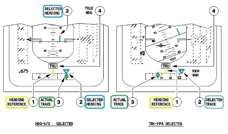
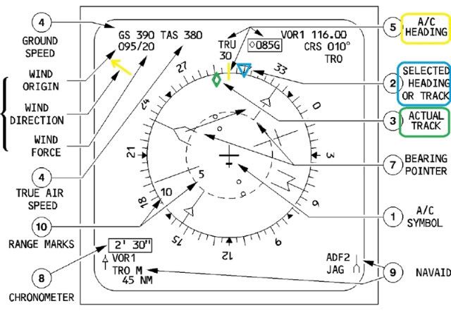
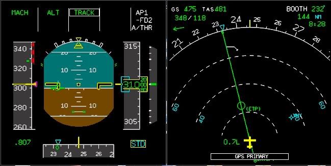
Not quite...the PFD and the ND have a full-time (green diamond) "track" symbol on the compasses so that the pilot can compare track with heading (blue triangle) and thus derive drift. Also, there is a full-time wind symbol on the ND, top-left.
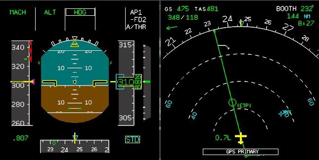
Clearly, (when not in NAV mode), in HDG/VS mode the Heading/Track symbol overlays the heading, (yellow lubber line at the top of the ND) and in TRK/FPA mode the Heading/Track symbol overlays the green diamond track symbol and lines up with the green track line, (4th graphic in HDG-VS, 5th in TRK-FPA). One can see the drift in either mode or even if the FD's are off as in this case. In NAV mode, the Heading/Track symbol is removed.
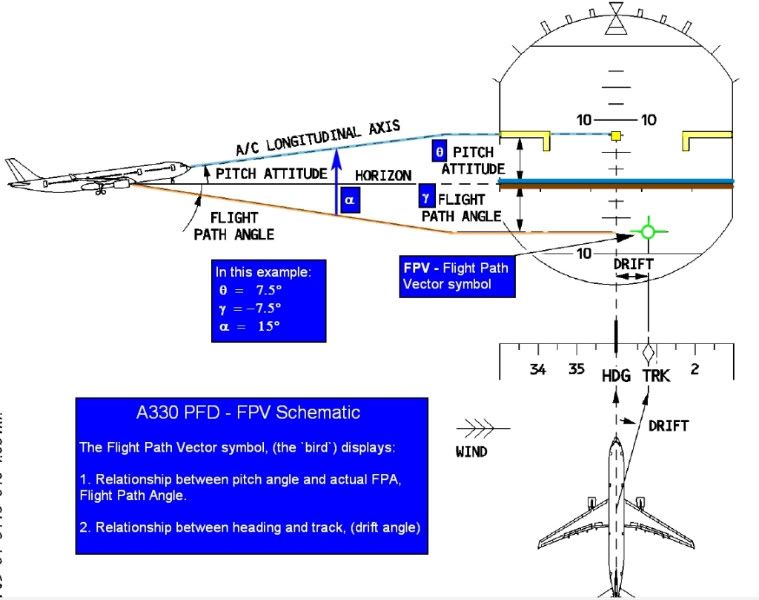
The presentation is visible at all times no matter what mode the FD is in, even if it's off. The bottom graphic shows the relationship between the Bird and the Track.
Here are three graphics which illustrate the symbols:
Hope this helps. Thanks for your note on the other thread.
PJ2
Meantime, and without the "Bird", a pilot has no heading (crab) reference,
Clearly, (when not in NAV mode), in HDG/VS mode the Heading/Track symbol overlays the heading, (yellow lubber line at the top of the ND) and in TRK/FPA mode the Heading/Track symbol overlays the green diamond track symbol and lines up with the green track line, (4th graphic in HDG-VS, 5th in TRK-FPA). One can see the drift in either mode or even if the FD's are off as in this case. In NAV mode, the Heading/Track symbol is removed.
The presentation is visible at all times no matter what mode the FD is in, even if it's off. The bottom graphic shows the relationship between the Bird and the Track.
Here are three graphics which illustrate the symbols:
Hope this helps. Thanks for your note on the other thread.
PJ2
Last edited by PJ2; 10th Aug 2010 at 07:55. Reason: add graphics/explanations
Join Date: Oct 2009
Location: W of Greenwich
Age: 78
Posts: 14
Likes: 0
Received 0 Likes
on
0 Posts
Scientific Report from the BEA Drift Group available
A report describing the BEA effort to model the tracks of the AF447 debris field prior to the Phase 3 at sea search is now available...
http://www.bea.aero/en/enquetes/flig...oup.report.pdf
http://www.bea.aero/en/enquetes/flig...oup.report.pdf
Guest
Posts: n/a
PJ2
Thank you for the excellent post and graphic. From memory (different computer), I recall an ACARS entry Re: FPV. Was it not selected and reported by the Flight Computer as unavailable? My assumption then is that the crew wished to select The FPV (bird) due to some need for it, in a cockpit that had become if not unintelligible, at least highly demanding? If flight data was displayed, and serviceable, augmenting the available cues with duplicative data might have been extraneous? The crew would have wanted to simplify the screens and distill the cues to regain control, no? The FPV u/s record fits with a screen that was either too busy or unavailable and a crew who were attempting a recovery from upset? The other possibility would be that the A/P trip happened after loss of control and the pilots may have been incapacitated due to the loads of uncontrolled flight and the computer volunteered an admission of degraded control/available instrumentation?
bear
bearfoil;
You're welcome - glad it's of use. Even though retired, the questions remain engaging.
I wouldn't place too much emphasis on the FPV selection or loss of the information, (which was likely due to loss of other systems). This is a relatively small piece of information which a crew, wrestling with rapidly unfolding occurences and a rapidly degrading situation, would not reach for.
No, I can't see this as part of any crews' thinking. "Screen clutter" is not an issue nor would one resolve this by de-selecting the FPV, (which re-selects HDG/VS).
AFAIK, with one exception, the DMUs do not become "too busy", (over-loaded) and thereby struggle to display information. That one exception is, (and I have seen it), when "Navaids" or "Waypoints" is selected for display and the scale of the ND is on 320nm. If there are a lot of these in the database, the display will sometimes flicker, but I think it is a non-issue in these circumstances.
Abnormal Attitude laws disconnect the A/P at 25degNU, 13degND and 50deg Bank, (if I recall correctly - not near my FCOM at the moment). Such attitudes are a long way from causing an incapacitation of the crew "due to the loads of uncontrolled flight". IOW, while such attitudes are extreme, they are still within the realm of crew controllability, while upside-down or pitch-vertical (up or down), would become a far greater challenge.
In terms of upset, "wings level" would come first, even before pitch, primarily because of the potential for spiral dive if wings are not first leveled. The exception, some will argue, may be in very high pitch angles where a "roll-off" to get the nose down first, may be more successful than a maximum-effort push-over. In any case, the FPV is not the information to be sought regarding these priorities as the primary guidance is attitude (closely followed by speed), in the moment, not trajectory which is what the FPV displays - in short, one uses as much sky as is necessary and available to return to controlled flight.
I think another way to put it might be, these are not moments where fine-tuning the response is a priority and such selections (or even paying attention to) lateral 'g' loads as indicated by the FPV, is not going to happen - unless heavily trained for and often (and we as an industry don't do this), the reaction (once past "startle") is more instinctual than measured.
I believe the crew had both PFDs (horizons) but stand to be corrected given the time that has passed since I read the reports.
Regarding rudders and fins, parts of the Canadian TSB Report on the Air Canada upset is worth reading I think.
Cheers,
PJ2.
You're welcome - glad it's of use. Even though retired, the questions remain engaging.
The FPV (bird) due to some need for it, in a cockpit that had become if not unintelligible, at least highly demanding? If flight data was displayed, and serviceable, augmenting the available cues with duplicative data might have been extraneous?
The crew would have wanted to simplify the screens and distill the cues to regain control, no?
The FPV u/s record fits with a screen that was either too busy or unavailable and a crew who were attempting a recovery from upset?
The other possibility would be that the A/P trip happened after loss of control and the pilots may have been incapacitated due to the loads of uncontrolled flight and the computer volunteered an admission of degraded control/available instrumentation?
In terms of upset, "wings level" would come first, even before pitch, primarily because of the potential for spiral dive if wings are not first leveled. The exception, some will argue, may be in very high pitch angles where a "roll-off" to get the nose down first, may be more successful than a maximum-effort push-over. In any case, the FPV is not the information to be sought regarding these priorities as the primary guidance is attitude (closely followed by speed), in the moment, not trajectory which is what the FPV displays - in short, one uses as much sky as is necessary and available to return to controlled flight.
I think another way to put it might be, these are not moments where fine-tuning the response is a priority and such selections (or even paying attention to) lateral 'g' loads as indicated by the FPV, is not going to happen - unless heavily trained for and often (and we as an industry don't do this), the reaction (once past "startle") is more instinctual than measured.
I believe the crew had both PFDs (horizons) but stand to be corrected given the time that has passed since I read the reports.
Regarding rudders and fins, parts of the Canadian TSB Report on the Air Canada upset is worth reading I think.
Cheers,
PJ2.
Last edited by PJ2; 10th Aug 2010 at 17:07. Reason: adding comments re FPV
Join Date: Jun 2009
Location: NNW of Antipodes
Age: 81
Posts: 1,330
Received 0 Likes
on
0 Posts
bearfoil - in reply to Post # 1847
RUDDER ANGLE
The acute angle between a water or airborne craft's fore-and-aft line and the current longitudinal center-line of the rudder.
Wrong! The graphic shows 7.9� of rudder angle at 272KCAS - the value that is "locked in" (when the flight law changed to Alternate) until slats extension, when it reverts to that available in Normal Law.
The 4.0� angle is that available at 350KCAS and beyond when in Normal Law, and would be the value "locked in" if an overspeed event had resulted in a change to Alternate or Direct Law. The 4.7� angle was included as a reference as to the angle at FL350 and M0.86 / 330KCAS.
Maximum rudder travel is therefore automatically limited as a function of aircraft KCAS to prevent structural overloading. In this respect, the "travel" is the angular deflection from the fore-and-aft line as described above. I haven't seen a schematic for the RTLU, but I suspect that a worm screw driven device creates a "feedback" position that inhibits hydraulic pressure to the operating rams beyond the set point. In this respect, the RTLU position is utilized by both port & starboard rams.
mm43
RUDDER ANGLE
The acute angle between a water or airborne craft's fore-and-aft line and the current longitudinal center-line of the rudder.
The Graph likewise shows a ~4degree angle consistent with RTLU default after Law Change for the assumed speed, 272 knots.
The 4.0� angle is that available at 350KCAS and beyond when in Normal Law, and would be the value "locked in" if an overspeed event had resulted in a change to Alternate or Direct Law. The 4.7� angle was included as a reference as to the angle at FL350 and M0.86 / 330KCAS.
Maximum rudder travel is therefore automatically limited as a function of aircraft KCAS to prevent structural overloading. In this respect, the "travel" is the angular deflection from the fore-and-aft line as described above. I haven't seen a schematic for the RTLU, but I suspect that a worm screw driven device creates a "feedback" position that inhibits hydraulic pressure to the operating rams beyond the set point. In this respect, the RTLU position is utilized by both port & starboard rams.
mm43
Join Date: Jun 2009
Location: NNW of Antipodes
Age: 81
Posts: 1,330
Received 0 Likes
on
0 Posts
cc45
Thanks for posting the link to the BEA's extensive report on how they determined the area to be searched during Phase 3. The report is complex and shows the difficulties that were faced in backtracking debris. For those who wish to wade through it, the link to the PDF file is:-
Phase 3 Search Zone Determination Report
Be warned - the file is large - 37MB.
mm43