


United B777 engine failure

I doubt you'd find many if any "injection molded" parts in a modern turbofan engine. The technologies used to make the parts are pretty universally high-tech and often state of the art. In the hot section, you'll find some pretty amazing technology used for both the turbine blades and nozzles - things like single crystal or directionally solidified part to eliminate or minimize grain boundaries in the parts. Fan blades used to be forged/machined solid titanium - however with the introduction of wide cord blades, the weight of solid TI became prohibitive - which lead to developments like the hollow fan blades used by Pratt and Rolls and the carbon composite used by GE.
3d printing is advancing rapidly, but I suspect we are still a ways from widespread use of 3d printed parts in commercial turbofan engines. When things like grain boundary's become critical to the performance and life of the part, 3d printing has a long way to go.
3d printing is advancing rapidly, but I suspect we are still a ways from widespread use of 3d printed parts in commercial turbofan engines. When things like grain boundary's become critical to the performance and life of the part, 3d printing has a long way to go.


Join Date: Dec 2010
Location: Middle America
Age: 84
Posts: 1,167
Likes: 0
Received 0 Likes
on
0 Posts
You may want to take a look at GE's 3-D printing sites on the internet. For example, the new GE90X engine for the Boeing 777X contains numerous 3-D printed parts including 3-D printed LPT blades. The engine has passed its initial certification to enable full flight testing this year. GE bought a company in Italy that developed the machines and processes for producing larger components such as the GE90X LPT blades now being produced. The developed processes have the same capability to produce LPT blades as rapidly as if they were cast, but with much more in terms of initial design freedoms.
Join Date: Dec 2010
Location: Middle America
Age: 84
Posts: 1,167
Likes: 0
Received 0 Likes
on
0 Posts

Join Date: Jun 2001
Location: Rockytop, Tennessee, USA
Posts: 5,898
Likes: 0
Received 1 Like
on
1 Post
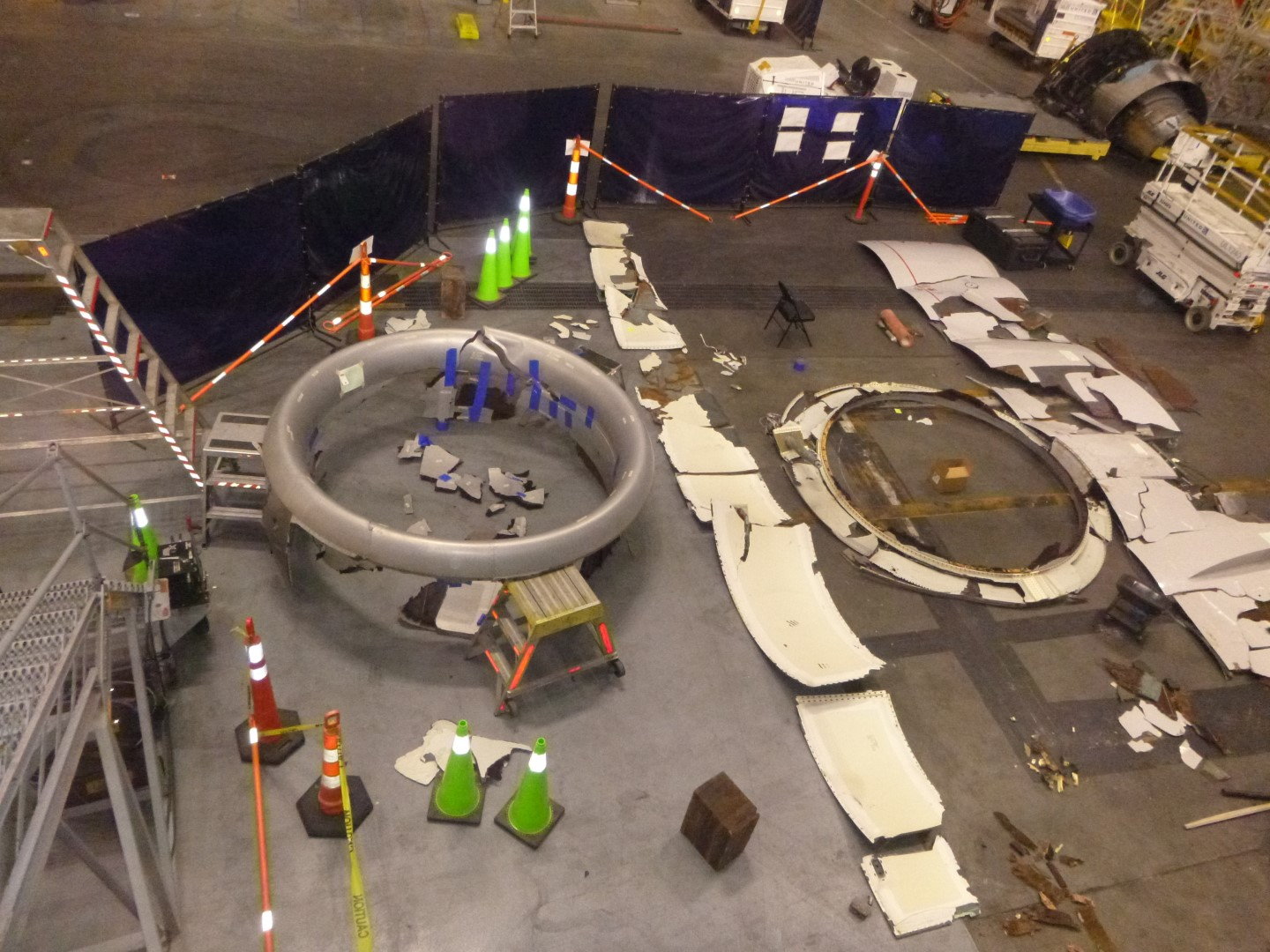
Today's NTSB media release with some pictures from the NTSB Flickr album.
The link to the latest NTSB Investigative Update: DCA21FA085 (ntsb.gov)
The link to the latest NTSB Investigative Update: DCA21FA085 (ntsb.gov)
NTSB News Release
National Transportation Safety Board Office of Safety Recommendations and Communications
NTSB Issues Investigative Update for United Airlines Flight 328 Engine Failure Event
3/5/2021
WASHINGTON (March 5, 2021) — The National Transportation Safety Board published an investigative update Friday for its ongoing investigation of the Feb. 20, 2021, United Airlines flight 328 engine failure event.
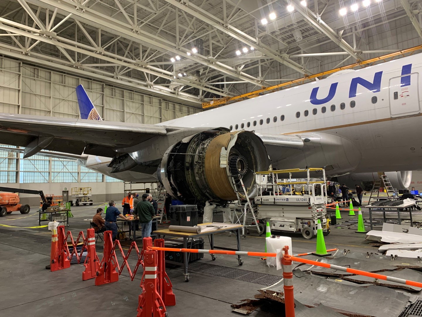
UAL flight 328 experienced a failure of the right Pratt & Whitney PW4077 engine shortly after takeoff from Denver International Airport, Denver. There were no injuries reported, and the airplane sustained minor damage.
The investigative update does not contain analysis and does not discuss probable cause in this ongoing investigation. As such, no conclusions regarding the cause of the engine failure should be made based on the information contained in the update. The information in the update is preliminary and subject to change as the investigation continues.
Facts gathered to date in the investigation, and provided in the update, include:
Initial examination of the right engine fire damage found it was primarily contained to the engine's accessory components, thrust reverser skin, and composite honeycomb structure of the inboard and outboard thrust reversers.
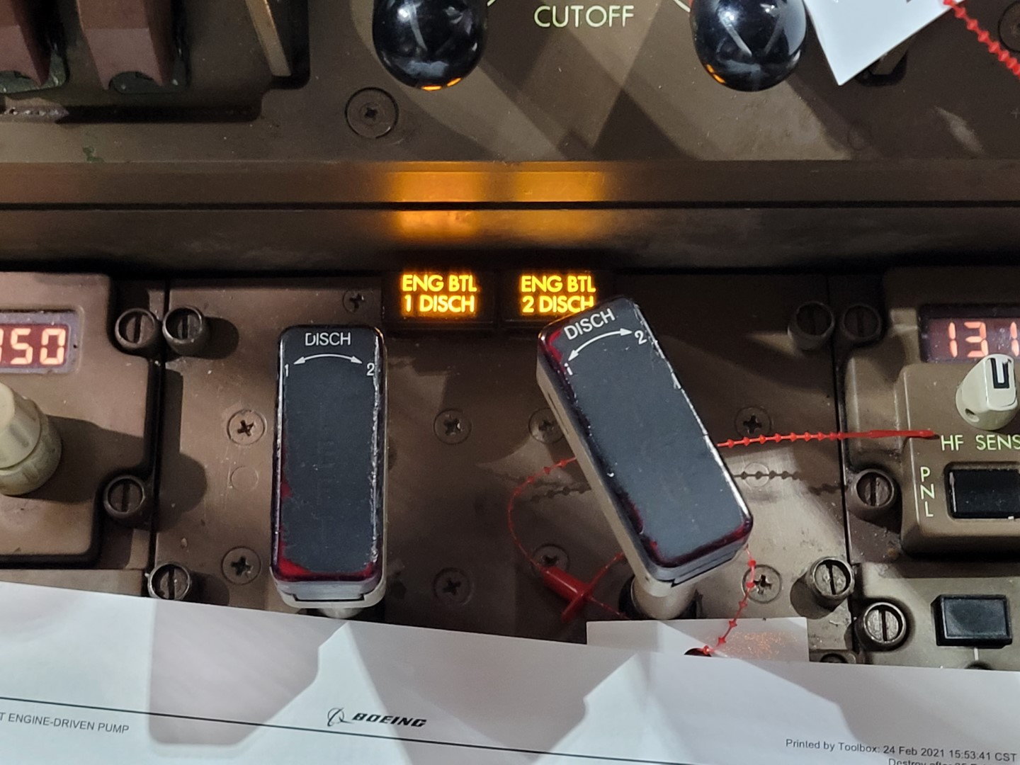
The spar valve, which stops fuel flow to the engine when the fire switch is pulled in the cockpit, was found closed – there was no evidence of a fuel-fed fire.
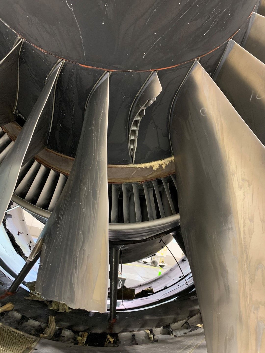
Initial examination of the right engine fan revealed the spinner and spinner cap were in place and appeared undamaged.
All fan blade roots were in place in the fan hub, two blades were fractured.
One fan blade was fractured 7.5 inches above the base at the trailing edge. The fracture surface was consistent with fatigue.
The second fractured blade exhibited indications of overload failure, consistent with secondary damage.
Initial review of maintenance and inspection data for the blade with the fatigue fracture, revealed it had experienced 2,979 cycles since its last inspection. This blade underwent thermal acoustic image inspections in 2014 and 2016. Inspection data collected from the 2016 inspection was examined again in 2018 because of a Feb. 13, 2018, incident involving a Boeing 777 with Pratt & Whitney PW4077 engines.
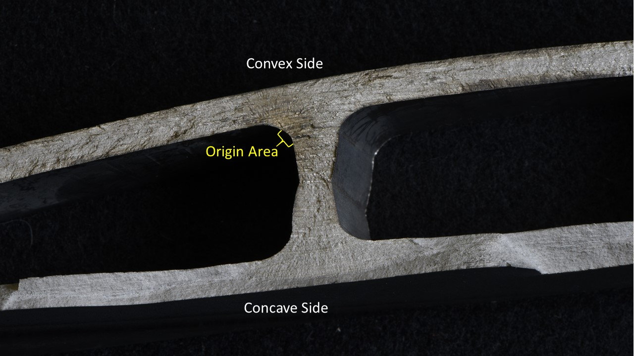
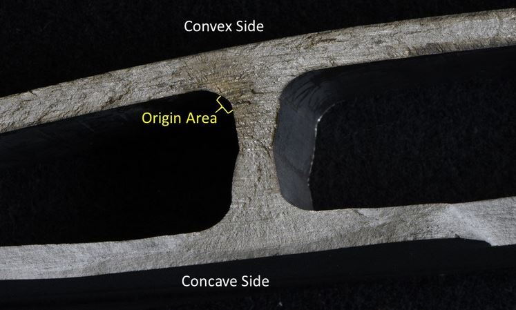
The engine fan blade with the fractures consistent with fatigue was sent to the metallurgical laboratory at Pratt & Whitney for further examinations led by a senior NTSB metallurgist. Preliminary findings from the scanning electron microscope examination identified multiple fatigue fracture origins on the interior surface of a cavity within the blade. Efforts to further characterize the fracture surface, including identifying the primary origin and counting striations, are ongoing. Additional work is underway to further characterize secondary cracks identified through fluorescent penetrant inspection. The NTSB metallurgy group also plans to analyze the blade's chemical composition and microstructure near the fracture surface.
The full investigative update is available online.
National Transportation Safety Board Office of Safety Recommendations and Communications
NTSB Issues Investigative Update for United Airlines Flight 328 Engine Failure Event
3/5/2021
WASHINGTON (March 5, 2021) — The National Transportation Safety Board published an investigative update Friday for its ongoing investigation of the Feb. 20, 2021, United Airlines flight 328 engine failure event.
UAL flight 328 experienced a failure of the right Pratt & Whitney PW4077 engine shortly after takeoff from Denver International Airport, Denver. There were no injuries reported, and the airplane sustained minor damage.
The investigative update does not contain analysis and does not discuss probable cause in this ongoing investigation. As such, no conclusions regarding the cause of the engine failure should be made based on the information contained in the update. The information in the update is preliminary and subject to change as the investigation continues.
Facts gathered to date in the investigation, and provided in the update, include:
Initial examination of the right engine fire damage found it was primarily contained to the engine's accessory components, thrust reverser skin, and composite honeycomb structure of the inboard and outboard thrust reversers.
The spar valve, which stops fuel flow to the engine when the fire switch is pulled in the cockpit, was found closed – there was no evidence of a fuel-fed fire.
Initial examination of the right engine fan revealed the spinner and spinner cap were in place and appeared undamaged.
All fan blade roots were in place in the fan hub, two blades were fractured.
One fan blade was fractured 7.5 inches above the base at the trailing edge. The fracture surface was consistent with fatigue.
The second fractured blade exhibited indications of overload failure, consistent with secondary damage.
Initial review of maintenance and inspection data for the blade with the fatigue fracture, revealed it had experienced 2,979 cycles since its last inspection. This blade underwent thermal acoustic image inspections in 2014 and 2016. Inspection data collected from the 2016 inspection was examined again in 2018 because of a Feb. 13, 2018, incident involving a Boeing 777 with Pratt & Whitney PW4077 engines.
The engine fan blade with the fractures consistent with fatigue was sent to the metallurgical laboratory at Pratt & Whitney for further examinations led by a senior NTSB metallurgist. Preliminary findings from the scanning electron microscope examination identified multiple fatigue fracture origins on the interior surface of a cavity within the blade. Efforts to further characterize the fracture surface, including identifying the primary origin and counting striations, are ongoing. Additional work is underway to further characterize secondary cracks identified through fluorescent penetrant inspection. The NTSB metallurgy group also plans to analyze the blade's chemical composition and microstructure near the fracture surface.
The full investigative update is available online.
Thanks
So although the fan blade failed (possibly prematurely) would be for P&W to investigate Boeing are looking into why the fan blade was able to remove the cowling and nacelle parts.
So although the fan blade failed (possibly prematurely) would be for P&W to investigate Boeing are looking into why the fan blade was able to remove the cowling and nacelle parts.

So these hollow blades fatigue from the inside, which makes finding the flaw really challenging. It would be informative to see the pictures of the fluorescent dye penetration tests done on these blades which indicated the incipient failure.
Join Date: Jan 2008
Location: uk
Posts: 857
Likes: 0
Received 0 Likes
on
0 Posts
May be some selection bias there - if the flaws we don't find are the ones on the inside which then lead to big news failures it doesn't follow that they always (or even mostly) fail that way, it may be that the other failure modes are more common but tend to get found on inspection so don't result in in-flight failure. We'd need to know the rate of prevented-failures (blade replacements) being caught by inspection.
Nevertheless, it seems like such (internal) cracks would be difficult to detect. Was this test/inspection methodology evaluated and proven on the basis of its effective detection of external and internal cracks?
but if they remain internal then the blade never fails
I think that a fatigue life-limit has to be developed here assuming a critical condition, unless of course if this is driven by an abnormal operating condition
still waiting a more clear assessment of this
I think that a fatigue life-limit has to be developed here assuming a critical condition, unless of course if this is driven by an abnormal operating condition
still waiting a more clear assessment of this
Exactly, the issue is whether an internal crack can potentially produce a catastrophic failure without externally visible manifestations.
If it can, fatigue life limits must be set appropriately, not an easy task.
If it can, fatigue life limits must be set appropriately, not an easy task.
Join Date: May 2011
Location: Finland
Age: 62
Posts: 16
Likes: 0
Received 0 Likes
on
0 Posts
True, but it seems that the fatigue crack has penetrated the surface and the fatigue region is quite long. It would be interesting to hear how long it took from the detectable "surface penetration" to the catastrophic failure.
JPcont:
From the UAL 1175 report:
"Beyond 0.032” deep from the origin was a region of predominantly fatigue striations, suggesting stable low cycle fatigue (LCF) propagation (Figures 17– 1 9). A striation count performed within a rectangular zone through this stable LCF region ~0.032” –0.153” from the origin estimated 5500 cycles of LCF crack propagation (Figure 20). The blade was last inspected via thermal acoustic imaging (TAI) ~1400 cycles ago in 2015. "
Join Date: Jul 2007
Location: Germany
Posts: 556
Likes: 0
Received 0 Likes
on
0 Posts
If it can, fatigue life limits must be set appropriately, not an easy task.
The assumption is that cracks which are too small to be found during TIA will not propagate during the inspection interval to a size that could make a blade fail in flight.
And you are right, setting this interval correctly is hard.
Last edited by bsieker; 8th Mar 2021 at 16:39. Reason: typo.
Thank you for this informative post
It suggests that the inspection process was ineffective at Pratt, which ties into the earlier reports that the signal was noted but dismissed as a flaw in the sensing material.
It suggests that the inspection process was ineffective at Pratt, which ties into the earlier reports that the signal was noted but dismissed as a flaw in the sensing material.
Join Date: Dec 2013
Location: UK
Posts: 22
Likes: 0
Received 0 Likes
on
0 Posts
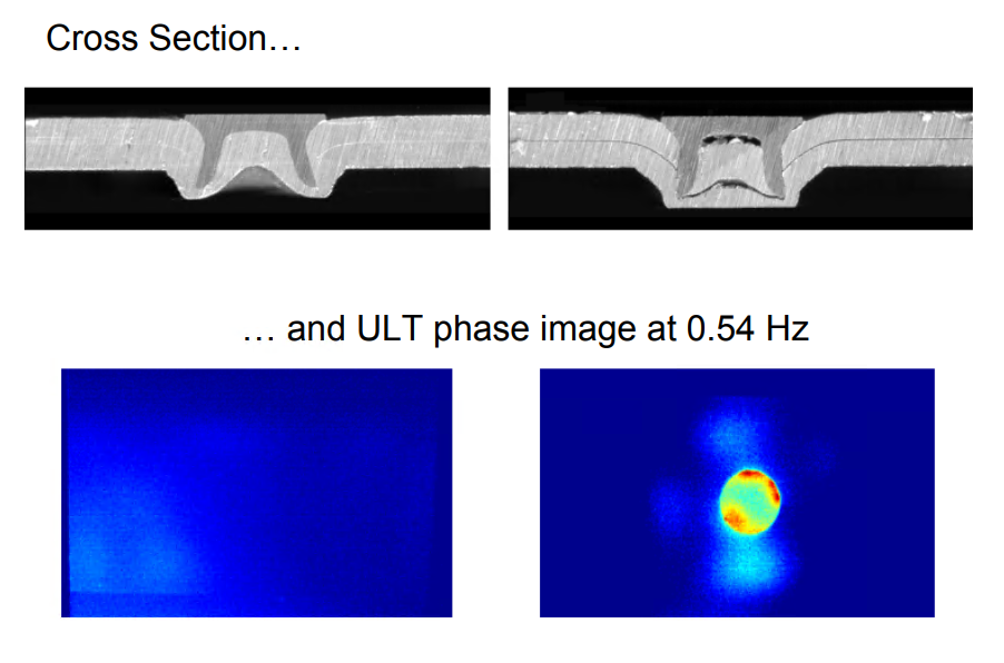
Dye pen can only be used on the outer surface. The method of flaw detection for internal surfaces is Thermal Acoustic Imaging (TAI). This is a P&W technique developed in 2005 for the specific purpose of finding internal fan blade cracking.
Join Date: Apr 2019
Location: EDSP
Posts: 334
Likes: 0
Received 0 Likes
on
0 Posts
Never heard of TAI - and what comes up on wikipedia does not seem to relate to metallurgy but to tissue materials.
So after some googling ... TAI seems to be a P&W internal/proprietary designation for ultrasound lockin thermography.
A body is excited by an ultrasound transducer which is then subjected to thermal imaging. Defects will create hotspots by friction in cracks.
So after some googling ... TAI seems to be a P&W internal/proprietary designation for ultrasound lockin thermography.
A body is excited by an ultrasound transducer which is then subjected to thermal imaging. Defects will create hotspots by friction in cracks.
Join Date: Jul 2007
Location: Germany
Posts: 556
Likes: 0
Received 0 Likes
on
0 Posts
That's thermoacoustic imaging. That wikipedia article links to the article about the P&W technique called thermal acoustic imaging.