


MAX’s Return Delayed by FAA Reevaluation of 737 Safety Procedures

Join Date: Mar 2006
Location: Vance, Belgium
Age: 62
Posts: 270
Likes: 0
Received 5 Likes
on
3 Posts
You are assuming that "The First-Officer has replied that the trim was not working" means that he attempted unsuccessfully to use the electric trim switches.
It could equally have been him just confirming that (as you rightly say) just over a minute previously both pilots had agreed to disable the stab trim (05:40:35), given that it was followed immediately by asking "if he could try it manually". In other words, the electric trim switches obviously weren't going to work, and there wouldn't have been any point in trying them.
It could equally have been him just confirming that (as you rightly say) just over a minute previously both pilots had agreed to disable the stab trim (05:40:35), given that it was followed immediately by asking "if he could try it manually". In other words, the electric trim switches obviously weren't going to work, and there wouldn't have been any point in trying them.
Further, I can't imagine that the FO answers "the trim is not working" without giving it a try.
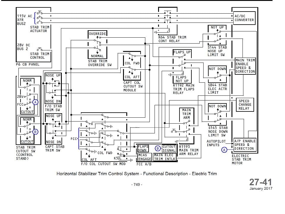
Besides, the electric wiring schematics are plain and clear ; the pedestal cutout switches disconnect the trim thumb switches from the 28V DC coming from the CB panel and the probe line running from the switches to the DFDAU can no longer record a variation of potential.
So, any attempt to operate these trim rockers after switching off the cutout could not have been recorded, as per the schematics.

Join Date: May 2019
Location: Somewhere over the rainbow...
Posts: 0
Likes: 0
Received 0 Likes
on
0 Posts
Join Date: Feb 2019
Location: shiny side up
Posts: 431
Likes: 0
Received 0 Likes
on
0 Posts
One thing I would note about the wiring diagram...the stab trim cutout switches...the way this is wired, it will not be a software fix to get back to the NG configuration. Most unfortunate.
Join Date: Feb 2019
Location: shiny side up
Posts: 431
Likes: 0
Received 0 Likes
on
0 Posts
In this switch config, it does not allow to separately turn off elec trim and AP trim.
I believe earlier it was discussed that the way MCAS is routed, it could be disabled by turning off the AP trim, but leave elec trim on, as it is more powerful way to move the elevator than manual trim....
Has that been shown to not be valid?
EDIT: corrected ref.
I believe earlier it was discussed that the way MCAS is routed, it could be disabled by turning off the AP trim, but leave elec trim on, as it is more powerful way to move the elevator than manual trim....
Has that been shown to not be valid?
EDIT: corrected ref.
Last edited by Smythe; 2nd Jul 2019 at 16:26.
Join Date: Jan 2008
Location: Weedon, UK
Age: 77
Posts: 125
Likes: 0
Received 0 Likes
on
0 Posts
You don't seem to want to tell us why you are so keen to shut down this area of discussion.

Join Date: Aug 2015
Location: UK
Posts: 0
Likes: 0
Received 0 Likes
on
0 Posts
There seem to be some misunderstandings about types of motors and their control so I think it may be worth providing a little bit of clarification. I'm not going to quote all the relevant comments on this, but I though this was worth repeating:
It seems pretty clear from the schematics and descriptions from Eaton that the contemporary motor unit works by turning the 400Hz 3 phase supply into DC and then the motor controller turns this back into a 3 phase supply at the frequencies required to achieve the various designed speeds. Control of speed control this way over quite a wide range is fairly easy with modern power electronics. This type of speed control is very similar to that in inverter drives for induction motors, and the motor stator will be pretty similar to that of a three phase induction motor, but the rotor is likely to be permanently magnetized rather than magnetized by induction. The motor may have a sensor that provides feedback to the controller as to current rotor position, but it is also possible for control circuits to deduce this from the current/voltage relationships in the three phases. However this is not the same as a servo motor.
A servo motor implies a system where a position (rather than speed) can be demanded and there is a feedback loop using a position sensor (traditionally an analogue potentiometer) to allow the controller to determine the current distance from the demanded position. Any type of motor could theoretically be used in such a system. Positional control can also be achieved using a stepper motor, which can be rotated in small steps of specific angle and will remain locked in that position unless the holding torque is exceeded. This can be open loop (relative motion from a starting point) or incorporated in a system with feedback.
50 years ago power electronics were much more primitive and it was therefore much more difficult to control motor speed over a wide range. However it has been said that pre NG there were two separate motors and I would guess they were both three phase AC motors which can be speed controlled using relays rather than power electronics, by switching the sequence of connections for the stator poles, but only in quite a limited range of integer ratios typically 2:1 or 3:1 which happen to be the same ratios seen above (0.4:0.2 and 0.27/0.09). Different gear ratios between the two motor rotors and the output shaft would explain the different Main Electric and Automatic speeds. Eventually along come robust power electronics and whatever speeds are required can be provided with just one motor and probably more reliably (less mechanical parts (bearings, gears and relays) to wear out).
1. The stab trim motor has four speeds - Main Electric fast/slow (0.4/0.2 deg/sec) and Automatic fast/slow (0.27/0.09 deg/sec) and two directions. If the previously posted schematics are to be taken at face value, then the commands for speed and direction come from outside the motor unit, but the actual processing of those commands into a specific speed and direction occur within a controller housed within the motor unit. While no documentation regarding this controller and how it operates has been publicly released, it is reasonable to assume that the accident investigating bodies would have access to it if they felt it was needed.
A servo motor implies a system where a position (rather than speed) can be demanded and there is a feedback loop using a position sensor (traditionally an analogue potentiometer) to allow the controller to determine the current distance from the demanded position. Any type of motor could theoretically be used in such a system. Positional control can also be achieved using a stepper motor, which can be rotated in small steps of specific angle and will remain locked in that position unless the holding torque is exceeded. This can be open loop (relative motion from a starting point) or incorporated in a system with feedback.
50 years ago power electronics were much more primitive and it was therefore much more difficult to control motor speed over a wide range. However it has been said that pre NG there were two separate motors and I would guess they were both three phase AC motors which can be speed controlled using relays rather than power electronics, by switching the sequence of connections for the stator poles, but only in quite a limited range of integer ratios typically 2:1 or 3:1 which happen to be the same ratios seen above (0.4:0.2 and 0.27/0.09). Different gear ratios between the two motor rotors and the output shaft would explain the different Main Electric and Automatic speeds. Eventually along come robust power electronics and whatever speeds are required can be provided with just one motor and probably more reliably (less mechanical parts (bearings, gears and relays) to wear out).
Join Date: Apr 2019
Location: EDSP
Posts: 334
Likes: 0
Received 0 Likes
on
0 Posts
to the collective body of professional accident investigators, multiple certificate authorities representing dozens of nations, subject matter experts, and other interested parties such as the aerospace-centric media (i.e. Aviation Week and the like) and the massive army of tort lawyers lining up to sue Boeing.
....
Time to move on.
....
Time to move on.
To the collective body of professional accident investigators, multiple certificate authorities representing dozens of nations, subject matter experts, and other interested parties such as the aerospace-centric media (i.e. Aviation Week and the like) and the massive army of tort lawyers lining up to sue Boeing:
Now as we know, that a fast speed trim runaway that cannot be stopped by counter trimming is considered a hazardous condition.
And now as we now that this Eaton actuator is a fancy modern microprocessor commutated and speed controlled brushless motor.
Could you please have a look if the actuators electronics - which is hardware and software - have been designed to a suitable design assurance level. Which would be
 DAL-B? DAL-A?
Uncontrolled dive is just a bit-flip away.
Thank you!
(Not suggesting any link to the two accidents though)
Last edited by BDAttitude; 2nd Jul 2019 at 19:09.
Join Date: Apr 2008
Location: Paris
Age: 74
Posts: 275
Likes: 0
Received 0 Likes
on
0 Posts
Oooh au contraire.
To the collective body of professional accident investigators, multiple certificate authorities representing dozens of nations, subject matter experts, and other interested parties such as the aerospace-centric media (i.e. Aviation Week and the like) and the massive army of tort lawyers lining up to sue Boeing:
Now as we know, that a fast speed trim runaway that cannot be stopped by counter trimming is considered a hazardous condition.
And now as we now that this Eaton actuator is a fancy modern microprocessor commutated and speed controlled brushless motor.
Could you please have a look if the actuators electronics - which is hardware and software - have been designed to a suitable design assurance level. Which would be DAL-B? DAL-A?
Uncontrolled dive is just a bit-flip away.
Thank you!
To the collective body of professional accident investigators, multiple certificate authorities representing dozens of nations, subject matter experts, and other interested parties such as the aerospace-centric media (i.e. Aviation Week and the like) and the massive army of tort lawyers lining up to sue Boeing:
Now as we know, that a fast speed trim runaway that cannot be stopped by counter trimming is considered a hazardous condition.
And now as we now that this Eaton actuator is a fancy modern microprocessor commutated and speed controlled brushless motor.
Could you please have a look if the actuators electronics - which is hardware and software - have been designed to a suitable design assurance level. Which would be
DAL-B? DAL-A?Uncontrolled dive is just a bit-flip away.
Thank you!
Edmund
Join Date: May 2019
Location: Somewhere over the rainbow...
Posts: 0
Likes: 0
Received 0 Likes
on
0 Posts
Commercial airline pilots generally don’t flip switches for the hell of it just to see what will happen or maybe because they thought it was a good idea at the time. Absent a specific procedure, we cannot even pull and/or reset circuit breakers if we think it would help. Case in point - remember that very distracting stick shaker that activated on both accident aircraft? The CB is right behind the Captain’s left shoulder, and pulling it would immediately silence the stick shaker. There is no authorized procedure to do so. Yes, the Captain always has emergency authority to do what he/she thinks is necessary, but the emphasis nowadays on sticking to the written procedures, and only the written procedures, is so prevalent that many Captains would be reluctant to go out on that limb.
It wasn’t always this way. There was a time when there was a much greater emphasis on systems knowledge. Not only were we expected to know a procedure, but we were expected to know why we were doing each step and what the implications were of every switch we threw and every control we actuated. We were give greater latitude to diverge from a procedure if, based on our knowledge of the underlying system, a different course of action was deemed more prudent. Those days are long gone.
Starting around the early 2000’s, if I recall correctly, our airline in concert with the manufacturers, started a process of “simplifying” a lot of our procedures, removing information regarding underling systems from our manuals, and largely discouraging any independent initiative or trouble-shooting that diverged from the written procedure. The rationale expressed at the time was 1) the concern that pilots could potentially create more problems than solve by troubleshooting, and 2) the desire to quickly contain any malfunction and get the aircraft on the ground. The change to how we handled Runaway Stab Trim was just one of the procedures caught up in this sea change. Part and parcel of the change in this procedure was also a change in the underlying level of system knowledge given to and expected from the pilots.
So you and a few other folks thinks the cutout switch logic should be returned to the NG configuration. I agree! However, that change does absolutely no good unless you go back to something like the earlier procedure. By its very nature, that procedure had more steps (and thus was harder to memorize), potentially took longer to execute because of the extra steps, and required a greater degree of knowledge of what was going on with the system.
Now you are entering my wheelhouse. As I’ve said repeatedly, these accidents not only revealed a design problem, they also revealed a training problem. Sure, give the pilots another tool to fight the malfunction, but that tool does absolutely no good if they don’t know how to use it. We have less detail about what went on in the cockpit of JT610, but we have a much better picture of ET302. Those pilots had, in theory, a specific set of tools available to them to help prevent the loss of control and a subsequent crash - foreknowledge (such as it was at the time) of MCAS, a working Main Electric Stab trim system, an Airspeed Unreliable procedure, and a Runaway Stab Trim procedure. None of these tools were used effectively.
Given this, my suggestion would be that rather than working on new tools, it might be more useful to determine why the existing tools were not properly employed.
Last edited by yoko1; 2nd Jul 2019 at 21:25.
Join Date: May 2019
Location: Somewhere over the rainbow...
Posts: 0
Likes: 0
Received 0 Likes
on
0 Posts
Neither of the formal investigations has yet produced a definitive report. Leaks, particularly those either defending or denigrating Boeing, serve only to muddy the waters, and are generally open to belief or ridicule as the reader sees fit. They certainly don't constitute evidence from "a party who actually has all the data, resources, and experts".
You don't seem to want to tell us why you are so keen to shut down this area of discussion.
You don't seem to want to tell us why you are so keen to shut down this area of discussion.
I could no more shut down this discussion than I can stop people from comparing notes on chemtrails if that’s what they want to do - but I just don’t see the logic behind it. I do think time and energy would be better spent elsewhere. But again, I do get the psychology of why some people want to hold onto this “hypothetical” as tightly as they do. Once you come to the conclusion that there was nothing amiss with the Main Electric Trim system, then that leads to a difficult conversation that some individuals would rather avoid.
Join Date: Dec 2014
Location: Somerset
Posts: 40
Likes: 0
Received 0 Likes
on
0 Posts
Cutout Switches
Sorry, a dumb question but electric circuits are a black art to me. I've seen this, or a similar diagram before, and am aware of all the comments that the two switches now peform an identical function. If that is the case, what is the function of the circuit 8 - 9 in the S272 Stab Trim Cutout Switch?
Thanks
Alchad
Thanks
Alchad
Join Date: May 2019
Location: United States
Posts: 0
Likes: 0
Received 0 Likes
on
0 Posts
(This was sarcasm in case it was not immediately apparent).
Join Date: Aug 2007
Location: Alabama
Age: 58
Posts: 366
Likes: 0
Received 0 Likes
on
0 Posts
If I read 27-41 correctly in Smythe's #951 post, the 8 -9 contacts are the FCC (and hence MCAS) route direct to the Eaton stab motor. As has been discussed this item is clearly more than just a motor and very little information about its architecture seems to be available. Terms such as 'processor based' could mean anything but are probably chosen carefully and probably don't mean microprocessor controlled. In my industry (nuclear) there are rigorous technical protocols for assessing and verifying embedded software on safety critical equipment and I'd be astonished if there is not something very similar in aerospace.
note that such controller does not have any input to any interlock...
Join Date: Dec 2018
Location: 8th floor
Posts: 0
Likes: 0
Received 0 Likes
on
0 Posts
If I read 27-41 correctly in Smythe's #951 post, the 8 -9 contacts are the FCC (and hence MCAS) route direct to the Eaton stab motor. As has been discussed this item is clearly more than just a motor and very little information about its architecture seems to be available. Terms such as 'processor based' could mean anything but are probably chosen carefully and probably don't mean microprocessor controlled. In my industry (nuclear) there are rigorous technical protocols for assessing and verifying embedded software on safety critical equipment and I'd be astonished if there is not something very similar in aerospace.
Yeah, the fact that the cutout switches are not wired identically in series is a bit strange. It's almost like somebody told the person responsible for the design "you have 5 minute to finish the damn thing, stop messing around with it and let's make it final, we have a deadline.". Anyway, about what the connections through the cutout switches seem to do:
1. connections 2 - 3 are wired in series between the two cutout switches, and are connected to the rest of the circuit in such a way that either of the cutout switches would do two things when used:
- interrupt the power between the circuit breakers and the thumb switches, making the thumb switches inoperable;
- de-energize the relay that connects the 3 phase 115V AC power to the trim motor, basically disconnecting the motor from AC power.
This means just cutting connection 2 - 3 on any of the two switches is enough to disable both manual and automatic electric trim.
2. connections 5 - 6 are wired in series as well between the two switches, and it seems that, if any of the two cutout switches are used, it would interrupt a 28V signal to the FCC, probably indicating to the FCC that the cutout switches have been used. No idea what the FCC will do based on that information.
3. connections 8 - 9 are wired only on the primary cutout switch, and as you said they seem to connect the FCC to the trim motor in some way. No idea why they don't go through the backup cutout switch as well, and exactly what signal they carry between the FCC and the motor. It almost looks like somebody forgot to route that connection through the second cutout switch. I don't see any reason for that.
Join Date: Feb 2019
Location: shiny side up
Posts: 431
Likes: 0
Received 0 Likes
on
0 Posts
So you and a few other folks thinks the cutout switch logic should be returned to the NG configuration. I agree! However, that change does absolutely no good unless you go back to something like the earlier procedure. By its very nature, that procedure had more steps (and thus was harder to memorize), potentially took longer to execute because of the extra steps, and required a greater degree of knowledge of what was going on with the system.
Does it warn of MCAS ENGAGE? (in the 'software' fix, I see they has AOA DISAGREE, where does it say MCAS ENGAGE as a warn?)
So I hit the cut switches, and have to manual trim..but now, I am too fast to manual trim with the nose pointed down.....before I could flip elec on and try to elec trim....
MCAS is not trim runaway...so what memory procedure is to be used? This is letting the tail wag the dog on fixing the situation.
Would an MCAS ENGAGE warn, with associated procedure, trim the response time?
The logic of the situation, the immediate response, as well as a longer term solution in flight, appears to show that switch configuration of the NG was better, not necessarily the best, but a better solution that the all cutout solution in the MAX, especially with the known manual trim wheel issues.
Looking at the switch config only, the NG config at least allows for elec trim when shutting off the AP...that has more value that trying to turn the manual wheel with its respective limitations.
Last edited by Smythe; 2nd Jul 2019 at 23:25.
Join Date: Aug 2007
Location: Alabama
Age: 58
Posts: 366
Likes: 0
Received 0 Likes
on
0 Posts
Since it appears that neither procedure has been trained, does it matter? Memorisation techniques?? Stick shaker and aural warnings...okay... why is the stick shaking....the stick is shaking for stall, but the trim wheels are spinning down?
Does it warn of MCAS ENGAGE?
MCAS is not trim runaway...so what memory procedure is to be used? This is letting the tail wag the dog on fixing the situation.
The logic of the situation, the immediate response, as well as a longer term solution in flight, appears to show that switch configuration of the NG was better, not necessarily the best, but a better solution that the all cutout solution in the MAX, especially with the known manual trim wheel issues.
Looking at the switch config only, the NG config at least allows for elec trim when shutting off the AP...that has more value that trying to turn the manual wheel with its respective limitations.
Join Date: Feb 2019
Location: shiny side up
Posts: 431
Likes: 0
Received 0 Likes
on
0 Posts
since the Captain has overall authority, why depriving him of the possibility to shut off HAL, if he choose so? Actually why that was the path chosen? I speculate that the airframe will have issues with certification if MCAS could be disable flipping a swtich!
The issue appears to be in the FBW scenario, my reference was being able to turn off AP functions, but maintain electrical control of the elevator, rather than manual control.
As it appears MCAS is an automated function, shut that down, but not elec control, right?
Or hell, call me crazy, fix the ac so it does not need MCAS to fly...oi vey!
Last edited by Smythe; 2nd Jul 2019 at 23:41.