


MAX’s Return Delayed by FAA Reevaluation of 737 Safety Procedures

I have no experience with that, so I can't comment on it, but at least in the x86 world you needed additional hardware to do that, for example DMA controllers. With PCI that changed, each PCI device could take control of the bus when it needed it, unless another device was using it. Of course it's not really that simple, there is still the chipset managing that and preventing conflicts.
There are a lot of variations on this theme, the most recent being I/O devices that can write directly to the CPU cache memory to improve performance even further. Anyway got too carried away, sorry for going off topic.
There are a lot of variations on this theme, the most recent being I/O devices that can write directly to the CPU cache memory to improve performance even further. Anyway got too carried away, sorry for going off topic.

Join Date: May 2019
Location: Somewhere over the rainbow...
Posts: 0
Likes: 0
Received 0 Likes
on
0 Posts
Perhaps the better question is this: When a pilot presses his yoke trim switch, does that action immediately energize the trim motor with current? Or, instead, is the pilot's action routed as an input to the trim computer, which actually controls the voltage applied to the trim motor? The difference could be fatal if the computer is too busy with other things to process the pilot's command first.
YYZjim
The automatic trim inputs (Speed Trim, Mach Trim, Autopilot) are a different matter.
Join Date: Nov 2018
Location: Vancouver
Posts: 68
Likes: 0
Received 0 Likes
on
0 Posts
The poor old processor got overloaded by data came from various sources? I think I posted somewhere that the new routine(s) associated with the MCAS data could overwhelm the control system from time to time, especially during the failure mode [i.e. vane's malfunction].
A series of simulator flights to test new software developed by Boeing revealed the flaw, according to one of the sources...
...In simulator tests, government pilots discovered that a microprocessor failure could push the nose of the plane toward the ground. It is not known whether the microprocessor played a role in either crash.
When testing the potential failure of the microprocessor in the simulators, "it was difficult for the test pilots to recover in a matter of seconds," one of the sources said. "And if you can't recover in a matter of seconds, that's an unreasonable risk.".
Boeing engineers are now trying to address the issue, which has led to another delay in recertifying the 737 Max...
===========
- https://edition.cnn.com/2019/06/26/p...law/index.html
New flaw discovered on Boeing 737 Max, sources say
...A new flaw has been discovered in the computer system for the Boeing 737 Max that could push the plane downward, according to two sources familiar with the testing, an issue that is expected to further delay the aircraft's return to service.A series of simulator flights to test new software developed by Boeing revealed the flaw, according to one of the sources...
...In simulator tests, government pilots discovered that a microprocessor failure could push the nose of the plane toward the ground. It is not known whether the microprocessor played a role in either crash.
When testing the potential failure of the microprocessor in the simulators, "it was difficult for the test pilots to recover in a matter of seconds," one of the sources said. "And if you can't recover in a matter of seconds, that's an unreasonable risk.".
Boeing engineers are now trying to address the issue, which has led to another delay in recertifying the 737 Max...
===========
- https://edition.cnn.com/2019/06/26/p...law/index.html
Join Date: Nov 2018
Location: Vancouver
Posts: 68
Likes: 0
Received 0 Likes
on
0 Posts
Also propagated by Reuters......Reuters, which first reported the new issue, said during an FAA pilot simulation in which the stall-prevention system was activated, it took longer than expected to recover the aircraft.
Other sources said the problem was linked to the aircraft's computing power and whether the processor lacked enough capacity to keep up.
Boeing said "we are working closely with the FAA to safely return the Max to service" and that it believed a software fix would address the problem.
But the FAA will be looking into whether it is a hardware issue.
If regulators are unsatisfied with the software fix, the microprocessor unit would have to be replaced and the grounding could stretch on for months longer than previously thought...
- https://www.bbc.com/news/business-48752932
Boeing suffers new 737 Max issue that could delay return
Other sources said the problem was linked to the aircraft's computing power and whether the processor lacked enough capacity to keep up.
Boeing said "we are working closely with the FAA to safely return the Max to service" and that it believed a software fix would address the problem.
But the FAA will be looking into whether it is a hardware issue.
If regulators are unsatisfied with the software fix, the microprocessor unit would have to be replaced and the grounding could stretch on for months longer than previously thought...
==========
- https://www.bbc.com/news/business-48752932
Thread Starter
Join Date: Apr 2015
Location: Under the radar, over the rainbow
Posts: 788
Likes: 0
Received 0 Likes
on
0 Posts
Whatever it may be, this is another "not reassuring" development, if the reports are accurate.
Last edited by OldnGrounded; 27th Jun 2019 at 02:08. Reason: Clarification

Join Date: Jun 2019
Location: leftcoast
Posts: 18
Likes: 0
Received 0 Likes
on
0 Posts
Old April AV Week re 'new' MCAS software
In view of the current ' discovery ' by FAA re microprocessor issue , this April long detailed article seems to provide some factual data. ??
Fred George Aviation Week & Space Technology Apr 11, 2019
To find a 'new' issue at this late date indicates BA needs some severe housecleaning..
Fred George Aviation Week & Space Technology Apr 11, 2019
Demo
Fred George Aviation Week & Space Technology Apr 11, 2019
Boeing has demonstrated the old and new versions of the MAX’s Maneuvering Characteristics Augmentation System (MCAS) to pilots and regulators in its 737 MAX engineering cab simulator in Seattle. The MCAS is a new flight-control-computer (FCC) function added to the MAX to enable it to meet longitudinal stability requirements for certification.
However, the system is only needed to enhance stability with slats and flaps retracted at very light weights and full aft center of gravity (CG). The aircraft exhibits sufficient natural longitudinal stability in all other parts of the flight envelope without the MCAS to meet the rules. Boeing emphasizes that the MCAS is not an anti-stall or stall-prevention system, as it often has been portrayed in news reports.
The new software load [P12.1] has triple-redundant filters that prevent one or both angle-of-attack (AOA) systems from sending erroneous data to the FCCs that could falsely trigger the MCAS. It also has design protections that prevent runaway horizontal stabilizer trim from ever overpowering the elevators. Boeing showed pilots that they can always retain positive pitch control with the elevators, even if they don’t use the left and right manual trim wheels on the sides of the center console to trim out control pressures after turning off the trim cut-out switches.
Most important, the MCAS now uses both left and right AOA sensors for redundancy, instead of relying on just one. The FCC P12.1’s triple AOA validity checks include an average value reasonability filter, a catastrophic failure low-to-high transition filter and a left versus right AOA deviation filter. If any of these abnormal conditions are detected, the MCAS is inhibited.
Three secondary protections are built into the new software load. First, the MCAS cannot trim the stabilizer so that it overpowers elevator pitch control authority. The MCAS nose-down stab trim is limited so that the elevator always can provide at least 1.2g of nose-up pitch authority to enable the flight crew to recover from a nose-low attitude. Second, if the pilots make electric pitch trim inputs to counter the MCAS, it won’t reset after 5 sec. and repeat subsequent nose-down stab trim commands. And third, if the MCAS nose-down stab trim input exceeds limits programmed into the new FCC software, it triggers a maintenance message in the onboard diagnostics system.
According to a pilot who was shown the changes in a simulator session, the demonstration begins with the original MCAS software load. During a normal takeoff, at rotation, the left AOA indication moves to its maximum reading—as seen from the flight data recorder in the Ethiopian Airlines accident. Pilots currently do not experience this during initial or recurrent simulator training. The stickshaker fires continuously, using loud sound and control wheel vibration to focus the pilot’s attention on the critically high AOA indication.
The erroneous AOA reading also creates large-scale indicated airspeed (IAS) and altitude errors on the primary flight display (PFD) which can be both distracting and disorienting.
AOA is used by the aircraft’s air data computers to correct pitot and static pressure variations induced by changes in nose attitude in relation to the relative wind. Large errors in AOA can cause 20-40-kt. errors in IAS and 200-400-ft. errors in indicated altitude. This is accompanied by the illumination of annunciators on both PFDs that warn of disparities in the IAS and altitude between the left and right displays. As part of the MCAS redesign, Boeing also is upgrading the MAX with AOA dial indicator displays and AOA disagree warning annunciators on the PFDs.
After the high-AOA indication, pilots then follow the checklist for “airspeed unreliable,” which assures that auto-pilot, auto-throttles and flight directors are turned off. They then pull back power to 80% fan speed, set 10-deg. nose-up pitch attitude and climb to 1,000 ft. above ground level. At that point, they lower the nose, start accelerating and begin retracting slats and flaps at 210 kt. indicated airspeed. When the slats and flaps are fully retracted—the MCAS kicks in.
“It’s a good thing we knew what to expect. Otherwise tunnel vision from the ‘airspeed unreliable’ event could have blinded us to the subsequent MCAS nose-down trim input. When I noticed the trim wheels racing, I grabbed the left wheel. It was easy to stop the trim with hand pressure, but I knew in advance what was happening,” says the pilot flying. “We followed the checklist for runaway stabilizer, checking again for auto-pilot off and auto-throttle off. We turned off both trim cut-out switches and cranked the ‘frisbees’ [manual trim wheels on both sides of the center console] to relieve control pressures. We used manual trim for the remainder of the flight to landing touchdown and rollout. That was quite an eye-opener, as I had never been exposed to that during sim training,” he notes.
It is critical to follow the checklist memory items: Pull back thrust to 75% after retracting slats and flaps and set attitude at 4 deg., nose up. If speed builds up beyond 220-250 kt., controllability becomes increasingly difficult, he adds.
Pilots for three U.S. air carriers tell Aviation Week that during their sim training they had never been exposed to extreme and continuous AOA indication errors, they’ve not experienced AOA induced airspeed and altitude deviations on PFDs and have not had to deal with continuous stall-warning stickshaker distractions. They also note that they have never been required to fly the aircraft from the point at which a runaway stab trim incident occurred all the way to landing using only the manual trim wheels. “We’re just checking boxes for the FAA,” says one Seattle-based pilot.
A full aerodynamic stall with the MCAS inoperative is another exercise pilots experience in the MAX engineering cab simulator. “We reduced thrust at 5,000 ft. and slowed the aircraft at about 1 kt. per sec. We were at a midrange cg [center of gravity] with gear, slats and flats up. We trimmed until we reached 30% above stall speed and then just continued to ease back on the control wheel,” one of the pilots says.
“Pitch feel was natural, progressively increasing as airspeed decayed. Somewhere between the audible low airspeed warning and stickshaker, I felt the slightest lightening on control pressure in my fingertips. Quite candidly, if I had not been watching for it, I don’t think I would have noticed any difference between the MAX and the Next Gen [NG] models. I kept pulling back through stickshaker, then buffet, then elevator feel shift [a function that doubles the artificial control feel forces near stall] and finally until the yoke was buried in my lap. The nose just flopped down gently at the stall, and I initiated recovery as I would in most other airplanes I’ve flown,” he adds.
During design of the MAX, Boeing added two more leading-edge vortilons [generating vortices over the top of the wing at high AOA] in 2018, for a total of six per side and also lengthened and raised the inboard leading-edge stall strips to assure stall behavior would be as docile as that of the NG.
Repeating many of the same maneuvers in the engineering cab simulator with the new software load would have been academic at best, as the triple-redundant AOA validity checks all but assure that the MCAS will not be triggered by erroneous AOA inputs in the future. But, FCC P12.1 changes do not protect against erroneous AOA causing stickshaker or large-scale distortions in indicated airspeed and altitude values. Those malfunctions still can cause distraction and disorientation, especially when flying at night and/or in instrument conditions.
The new MCAS protections built into the P12.1 software load preserve its essential role in enhancing the MAX’s longitudinal stability, while virtually guaranteeing that it won’t be triggered by erroneous AOA. And when it does activate, its nose-down stabilizer trim command authority will be limited to assure the pilots always can control aircraft pitch with the elevators.
However, the FCC software upgrades are not the only critical changes needed to boost safety margins for operators. Pilots who underwent the demonstration also say the sessions underscored the need for additional simulator training for dealing with compound emergencies involving AOA and runaway trim failures.
Join Date: Feb 2019
Location: shiny side up
Posts: 431
Likes: 0
Received 0 Likes
on
0 Posts
FDR...verbose as you are , it is not correct on many fronts..
That is what I stated, stick feel is a result of aerodynamics, not the other way around...
You misquoted what I stated. Surfaces do go transonic, I did not mention only low speed, but high AOA...Boeing does mention low speed stall, AND high AoA AND high G ....not inclusive. Many surfaces go transonic on the wing, fuselage and cowlings...
Boeing DOES state that in testing, they found airflow over the wing went transonic, and tried to alleviate this issue with vortex tabs and changing the wing design...Boeing own words, not mine.
No laminar flow over the wing??? Really...explain this video:
Again, as verbose as that is, how does it relate to the MAX stalling at relatively low AoA comparatively? On low speed final, it pushes the nose down 2.5 degrees to avoid stall...what AoA are you at on final?
.
Of course, that is why they still have vortex tabs running down the wing....but you say this cures issues of separation, but deny laminar flow over the wing?
But we do appear to agree that he stick feel is a result, correct?
We are over 105 days on the grounding, and the FAA found another issue. Perhaps unstable is a bit harsh, but certainly, in many conditions , it is not predictable....
What if MCAS is far more reaching than Boeing has stated? It certainly appears to be. Perhaps the half FBW design has inherent flaws that were either unintended or incorrectly implemented in the software?
Again, over 100 days says that MCAS may be a lot more active than anticipated.
I completely agree the pilots deserve more. I also think that there are many unintended consequences that can line up in the software...and MCAS is far more active than thought...again, over 100 days, and still finding issues....
How is the low speed stall issue, not a stall issue? Stick pressure was not mentioned, simply low speed stall. MCAS was designed to push the nose down 2.5 degrees to prevent stall. Where is the interpretation here? 0.6 pitch up on DEP, okay, some lift and stick feel, but jeez, 2.5 on final? (of course, as we all know, its all 2.5 now) What about high G? Where the heck does MCAS come into play in this scenario?
1. "I am looking at what was stated, and provide the aerodynamic reasoning behind it. Forget about stick feel."
stick force is a consequence of aerodynamics, control system architecture and modifiers.
stick force is a consequence of aerodynamics, control system architecture and modifiers.
2. (A) "...going supersonic..."
High AOA is inconsistent with high mach numbers in general, wings tend to fall off Par 25 planes when pulling high AOA at high mach, available AOA is constrained by buffet in such cases, so the terminology used is vague... At low speeds, there is no transonic flow on a BAC447-450 type section at any AOA. The BAC airfoil section may have gone supersonic in the Silk air bingle, and possibly Adam Air splash, but otherwise it is rather unlikely to get to a point where the section is supersonic, e.g., has an oblique shock formation. It will usually have a normal shock at around 0.5c-0.6c in cruise, at say M0.78 and above, at 2.3 AOA.
High AOA is inconsistent with high mach numbers in general, wings tend to fall off Par 25 planes when pulling high AOA at high mach, available AOA is constrained by buffet in such cases, so the terminology used is vague... At low speeds, there is no transonic flow on a BAC447-450 type section at any AOA. The BAC airfoil section may have gone supersonic in the Silk air bingle, and possibly Adam Air splash, but otherwise it is rather unlikely to get to a point where the section is supersonic, e.g., has an oblique shock formation. It will usually have a normal shock at around 0.5c-0.6c in cruise, at say M0.78 and above, at 2.3 AOA.
Boeing DOES state that in testing, they found airflow over the wing went transonic, and tried to alleviate this issue with vortex tabs and changing the wing design...Boeing own words, not mine.
(B) "...lack of laminar flow...";
irrespective of what is being smoked, and how much was spent on the design, there is no laminar flow worth noting on any RPT jet transport. If you want laminar flow, go and look at a standard sail plane. the slat TE destroys laminar flow, as does the first rivet head, screw head etc that exists on the slat. For the first 1% of the chord, which more or less is in the radius of the LE, around the Kutta point, there may be laminar flow dependent on when the plane was last washed. FYI, the slat TE eats up the boundary layer, it is a discontinuity in the surface, and causes separation in the presence of a shear, and that always gives an initial span-wise vortex structure which is highly unstable as is any flow behind an aft facing step... That vortex structure starts to shed with a Strouhal number that is identifiable as a harmonic of the how frequency vibration that arises from the instability of the normal shock and the associated SBLI foot, which is observable oscillating on the wing in steady flight. Look out the window with the sun aligned down the mid chord span and you will have a Schlieren iamge of the shadow of the densty change in the foot of the shock. In essence, at any time, your Boeing, or Bus doesn't have laminar flow anywhere except in the idealised models of the airfoil in simplified CFD modelling. Sorry. That is not to say it can't be improved...
irrespective of what is being smoked, and how much was spent on the design, there is no laminar flow worth noting on any RPT jet transport. If you want laminar flow, go and look at a standard sail plane. the slat TE destroys laminar flow, as does the first rivet head, screw head etc that exists on the slat. For the first 1% of the chord, which more or less is in the radius of the LE, around the Kutta point, there may be laminar flow dependent on when the plane was last washed. FYI, the slat TE eats up the boundary layer, it is a discontinuity in the surface, and causes separation in the presence of a shear, and that always gives an initial span-wise vortex structure which is highly unstable as is any flow behind an aft facing step... That vortex structure starts to shed with a Strouhal number that is identifiable as a harmonic of the how frequency vibration that arises from the instability of the normal shock and the associated SBLI foot, which is observable oscillating on the wing in steady flight. Look out the window with the sun aligned down the mid chord span and you will have a Schlieren iamge of the shadow of the densty change in the foot of the shock. In essence, at any time, your Boeing, or Bus doesn't have laminar flow anywhere except in the idealised models of the airfoil in simplified CFD modelling. Sorry. That is not to say it can't be improved...
(C ) "...induces a stall..."
not the way flow works. Sorry. A turbulent BL has one benefit over laminar and that is it can cope with adverse pressure gradient perturbations before becoming messy. Flow behind a shock is separated near the surface, but that is not a stall as such, which is defined in the regs... as a number of specific conditions that occur. separation may be a pain, particularly geographic ones, but it is a normal part of life. Stalls are stalls... per the regs. Taking your comment to an extreme, pulling say 10 AOA at M0.82 will still not end up in a stall, it will take the wings right off the aircraft, but before you get to that point, flow separation will have resulted in severe buffet, and reducing Cl/AOA, which put you back toward the beginning...
not the way flow works. Sorry. A turbulent BL has one benefit over laminar and that is it can cope with adverse pressure gradient perturbations before becoming messy. Flow behind a shock is separated near the surface, but that is not a stall as such, which is defined in the regs... as a number of specific conditions that occur. separation may be a pain, particularly geographic ones, but it is a normal part of life. Stalls are stalls... per the regs. Taking your comment to an extreme, pulling say 10 AOA at M0.82 will still not end up in a stall, it will take the wings right off the aircraft, but before you get to that point, flow separation will have resulted in severe buffet, and reducing Cl/AOA, which put you back toward the beginning...
4. Look at what they tried to do, adding vortex tabs, changing the wing design....
That is what happens with almost all designs, including Busses etc. The dog tooth on the Bus arises from a surprise in testing... VG's are a good tool for curing issues of separation and shock issues, they don't cook means well, but they have their uses. I would be happier if they did do more work on the wing, there is a lot of room for improvement on all of these designs which are the industrial engineers mass produced product rather than the ASW-21 or other embodiment of elegant design
That is what happens with almost all designs, including Busses etc. The dog tooth on the Bus arises from a surprise in testing... VG's are a good tool for curing issues of separation and shock issues, they don't cook means well, but they have their uses. I would be happier if they did do more work on the wing, there is a lot of room for improvement on all of these designs which are the industrial engineers mass produced product rather than the ASW-21 or other embodiment of elegant design
Of course, that is why they still have vortex tabs running down the wing....but you say this cures issues of separation, but deny laminar flow over the wing?
5. "...Changing the wing design?? Do you change the wing design to make the stick pressure the same, or to prevent stall? The differential pressure on the yoke is a RESULT of the stall..."
There are a number of manners that the design could be tweaked in testing to attempt to achieve compliance with the stick force gradient requirements. As commented above, removing the strake would get rid of the issue, but comes at a cost, whereas MCAS had no cost had it been implemented competently. There are designs out there that have specific application of VGs to meet the same requirement. Almost every aircraft on the ramp has flow modifiers on them, and they are all specific in their application, what the defect was that was underlying their implementation. Each conventional VG has a drag count penalty, according to NASA research of around 0.0002Cd, so they are used sparingly and only when the gain from their use offsets the Cd increase from their installation. Not sure what a differential pressure on a yoke refers to, I only speak english, but if you are referring to the stick force gradient non linearity, that is not caused by stall. Consider that any premature stall around the nacelle will actually improve handling qualities of any aircraft; it will ensure that the lateral control requirements are met, that the aircraft will pitch down, that buffet on the airframe from impingement of wake on the stab and elevators is more likely to be encountered. These are good things. The GTF nacelle doesn't cause a premature stall, it does the opposite... Now if the wing tips stall, then you get great entertainment, and that is not the problem, nor would it arise from the nacelle.... Think of why simple wings have wash out, and why dog tooths, VG's vortilons etc are used on swept wing aircraft. I don't think I agree with your paragraph on that matter...
There are a number of manners that the design could be tweaked in testing to attempt to achieve compliance with the stick force gradient requirements. As commented above, removing the strake would get rid of the issue, but comes at a cost, whereas MCAS had no cost had it been implemented competently. There are designs out there that have specific application of VGs to meet the same requirement. Almost every aircraft on the ramp has flow modifiers on them, and they are all specific in their application, what the defect was that was underlying their implementation. Each conventional VG has a drag count penalty, according to NASA research of around 0.0002Cd, so they are used sparingly and only when the gain from their use offsets the Cd increase from their installation. Not sure what a differential pressure on a yoke refers to, I only speak english, but if you are referring to the stick force gradient non linearity, that is not caused by stall. Consider that any premature stall around the nacelle will actually improve handling qualities of any aircraft; it will ensure that the lateral control requirements are met, that the aircraft will pitch down, that buffet on the airframe from impingement of wake on the stab and elevators is more likely to be encountered. These are good things. The GTF nacelle doesn't cause a premature stall, it does the opposite... Now if the wing tips stall, then you get great entertainment, and that is not the problem, nor would it arise from the nacelle.... Think of why simple wings have wash out, and why dog tooths, VG's vortilons etc are used on swept wing aircraft. I don't think I agree with your paragraph on that matter...
6. Stick pressure? I feel that is a half baked response by Boeing to mask the problems with the aerodynamics of the wing/engine design, and simply does not make sense. Maybe that is how is was presented to the FAA, but I dont think that is reality. Boeing will never admit that the aircraft was not aerodynamically stable.
If the aircraft was unstable at any point, which is pretty hard to see how that would be achievable, given the margins that exist between the normal aft envelope and the neutral point, then in any case, no TP would have signed off on the acceptability of the aircraft. It is a very straight forward matter to ascertain if the design is or was unstable, and for the record the data that has been published already is sufficient to show that the aircraft was statically and dynamically stable. Long ago I looked at an RPT aircraft that was on the limit of stability in flight, and it is not hard to detect in the data. THE MAX IS NOT UNSTABLE. PERIOD. Don't take my word for it, look at the public domain data on the control inputs. It had a trim issue, and that is all.
If the aircraft was unstable at any point, which is pretty hard to see how that would be achievable, given the margins that exist between the normal aft envelope and the neutral point, then in any case, no TP would have signed off on the acceptability of the aircraft. It is a very straight forward matter to ascertain if the design is or was unstable, and for the record the data that has been published already is sufficient to show that the aircraft was statically and dynamically stable. Long ago I looked at an RPT aircraft that was on the limit of stability in flight, and it is not hard to detect in the data. THE MAX IS NOT UNSTABLE. PERIOD. Don't take my word for it, look at the public domain data on the control inputs. It had a trim issue, and that is all.
7. Is MCAS operational in AP? While I keep hearing the mantra, it only operation with AP off, it appears it is operational according to several reports that show turning off the AP resolves the problem. Wasnt it the case with the last crash, that when they turned AP back on, MCAS engaged again?
Again, as the aircraft IS NOT UNSTABLE, an autopilot doesnt need MCAS to meet any stick force per g compliance matters. That is the first big clue that the issue is and has always been about the force gradient compliance. MCAS would be redundant, a double negative, nonsense for an autopilot engaged condition.
Again, as the aircraft IS NOT UNSTABLE, an autopilot doesnt need MCAS to meet any stick force per g compliance matters. That is the first big clue that the issue is and has always been about the force gradient compliance. MCAS would be redundant, a double negative, nonsense for an autopilot engaged condition.
8. "....In one incident, an airline pilot reported that immediately after engaging the Max 8’s autopilot, the co-pilot shouted “DESCENDING,” followed by an audio cockpit warning, “DON’T SINK! DON’T SINK!”
Autopilots are born of man (or woman etc... )per the bard and fail. The reported issue was a pitch down excursion which is an event that is required to be covered in certification, being an aspect that is considered in the minimum engagement and disengagement heights for autopilots. Had the MCAS not resulted in public misinformation and hysteria, then this particular matter would have been kept in its proper place, that being an APFD anomaly, with no association to the MCAS issue.
Autopilots are born of man (or woman etc... )per the bard and fail. The reported issue was a pitch down excursion which is an event that is required to be covered in certification, being an aspect that is considered in the minimum engagement and disengagement heights for autopilots. Had the MCAS not resulted in public misinformation and hysteria, then this particular matter would have been kept in its proper place, that being an APFD anomaly, with no association to the MCAS issue.
9. “I immediately disconnected AP (Autopilot) (it WAS engaged as we got full horn etc.) and resumed climb,” the pilot writes in the report, which is available in a database compiled by NASA. “Now, I would generally assume it was my automation error, i.e., aircraft was trying to acquire a miss-commanded speed/no autothrottles, crossing restriction etc., but frankly neither of us could find an inappropriate setup error (not to say there wasn’t one).
The crews getting into the Max deserved more than an Ipad briefing. However, the comment on the APFD anomaly has nothing to do with MCAS.
The crews getting into the Max deserved more than an Ipad briefing. However, the comment on the APFD anomaly has nothing to do with MCAS.
10. In reality, MCAS is anti-stall.
Nope, not even close. Refer preceding.
Nope, not even close. Refer preceding.
As far as the main electric trim (activated by the yoke trim switch), it's all switches and relays as far as the electric part of it goes. No computers needed. Keep in mind that the basic 737 design goes back 50 years, so Boeing figured out how to do a lot of things without IC chips. There have been updates along the way, of course, but the main electric trim system is pretty robust and reliable.
The automatic trim inputs (Speed Trim, Mach Trim, Autopilot) are a different matter.
The automatic trim inputs (Speed Trim, Mach Trim, Autopilot) are a different matter.
* I have used the word 'override' but I think 'cancel' might be better in the case of MCAS, or even postpone!
This is an unfortunate development in the process, but two positives exist, 1; the new issue has been discovered before RTS, and 2; it has been acknowledged.
TBC can spend a lot of time sorting out the hardware on this, and probably about the same in getting a software solution, or they could add an interrupt off the ANU side of the trim switches to de-power MCAS in all cases. An isolating system using existing switches would be a quick but dirty solution to the problem. The lights will be burning in Seattle, and hopefully the lighting bill is paid for by stopping paying to lawyers and putting the funds into the company where it is needed, solving the problems of expediency.
TBC can spend a lot of time sorting out the hardware on this, and probably about the same in getting a software solution, or they could add an interrupt off the ANU side of the trim switches to de-power MCAS in all cases. An isolating system using existing switches would be a quick but dirty solution to the problem. The lights will be burning in Seattle, and hopefully the lighting bill is paid for by stopping paying to lawyers and putting the funds into the company where it is needed, solving the problems of expediency.
Join Date: Feb 2019
Location: shiny side up
Posts: 431
Likes: 0
Received 0 Likes
on
0 Posts
From NPR on the latest...is this getting back to the trim wheel issue?
"Boeing has developed a software fix for that flight control system, called MCAS, but sources familiar with the situation tell NPR that in simulator testing last week, that FAA test pilots discovered a separate issue that affected their ability to quickly and easily follow recovery procedures for runaway stabilizer trim and stabilize the aircraft."
"Boeing has developed a software fix for that flight control system, called MCAS, but sources familiar with the situation tell NPR that in simulator testing last week, that FAA test pilots discovered a separate issue that affected their ability to quickly and easily follow recovery procedures for runaway stabilizer trim and stabilize the aircraft."
Join Date: May 2008
Location: denmark
Posts: 9
Likes: 0
Received 0 Likes
on
0 Posts
I had seen this coming..
MAX’s Return Delayed by FAA Reevaluation of 737 Safety Procedures
This needed computer hardware upgrade might be related to the risks of having a DAL C architecture instead of a DAL A architecture. (And the difference in failure rate)
With the DAL C architecture the pilot have to perform the fault isolation (since the failure rate is to high), and if that are not reacting fast enough they need to be able mussel the aircraft back in control from a full run-away within the envelope.
This is needed to fulfill CS 25.671.
A DAL A architecture can in principle remove the need for trim wheel and cutout switches (if they want to go this route)
This is likely one source of misunderstanding here, as there are many posters here unable to fully comprehend why the grounding is ongoing or what the long delay is a result of.
In the absence of conclusive evidence that demonstrates with absolute certainty that the main electric trim system was 100% operative throughout all phases of both fatal accidents [for the record, there is none], investigators are left drawing probable conclusions based on the available evidence:
1> It is not very plausible that two separate crews comprised four trained, experienced, pilots all elected not to attempt to trim ANU (more than a sub-second blip) when presented with life-threatening ongoing opposing trim in clear conditions in sight of the ground, whilst simultaneously commanding nose up at forces likely not previously experienced.
2> The "blips" are present in the last seconds of both fatal accidents.
3> The "blips" are consistent with an initial ANU trim command, but each has no resulting actual ANU trim of any significance whatsoever, certainly nothing like that required to improve the situation they were presented with. See 1> above.
4> The "blips" are entirely consistent with a shorted and/or overpowered motor.
5> The "blips" look exactly as we would expect a command to an overpowered motor to record; a power spike then null.
6> The manual trim was also overpowered under the aerodynamic loads experienced at that time.
7> "Trim with me" is not the announcement one would expect to be made by a PF who's trim is functioning correctly.
8> The actions of the MS crew, including attempting to briefly trim AND in such a situation, are consistent with a crew dealing with an inoperable main electric trim in the ANU moment.
9> Both crews were aware that an 'auto' trim was trimming against them but were ultimately unable to prevent their aircraft from trimming them into the ground to their certain death and the demise of all onboard.
10> XAA's all around the world have grounded all aircraft of this type until further notice.
I could go on, however... given just the above, and all the other facts as known at this time, we can safely conclude that ON THE BALANCE OF PROBABILITY the main electric trim was totally inoperable in the ANU moment during the last seconds or minutes of the fatal accidents.
That conclusion inexorably leads to some uncomfortable truths, and it is understandable that many here do not wish to go there. But, just as the Soviets learnt the hard way at Chernobyl, in the end, only by shining a bright light on all of the flaws can real progress be made towards rectification.
This aircraft remains grounded worldwide until that happens, despite protestations otherwise, whether on this forum or elsewhere.
“oh contraire” (sic):
The trim rim inputs are recorded separate from the THS movement. In both flights there were longer periods of manual inputs resulting in longer movements of the THS. In both flights towards the end there were short manual inputs followed by small THS movement. In both flights following manual inputs there was MCAS trimming AND. At no point in the FDR readout was there a prolonged manual input followed by no movement of the THS (the real indicator of an overpowered trim motor).
The balance of probability is there is an absence of knowledge on your part, and an overwhelming amount of long words to compensate for that.
FDR...verbose as you are , it is not correct on many fronts..
That is what I stated, stick feel is a result of aerodynamics, not the other way around...
You misquoted what I stated. Surfaces do go transonic, I did not mention only low speed, but high AOA...Boeing does mention low speed stall, AND high AoA AND high G ....not inclusive. Many surfaces go transonic on the wing, fuselage and cowlings...
Boeing DOES state that in testing, they found airflow over the wing went transonic, and tried to alleviate this issue with vortex tabs and changing the wing design...Boeing own words, not mine.
No laminar flow over the wing??? Really...explain this video:
https://www.youtube.com/watch?v=HekbC6Pl4_Y
Again, as verbose as that is, how does it relate to the MAX stalling at relatively low AoA comparatively? On low speed final, it pushes the nose down 2.5 degrees to avoid stall...what AoA are you at on final?
.
Of course, that is why they still have vortex tabs running down the wing....but you say this cures issues of separation, but deny laminar flow over the wing?
But we do appear to agree that he stick feel is a result, correct?
We are over 105 days on the grounding, and the FAA found another issue. Perhaps unstable is a bit harsh, but certainly, in many conditions , it is not predictable....
What if MCAS is far more reaching than Boeing has stated? It certainly appears to be. Perhaps the half FBW design has inherent flaws that were either unintended or incorrectly implemented in the software?
Again, over 100 days says that MCAS may be a lot more active than anticipated.
I completely agree the pilots deserve more. I also think that there are many unintended consequences that can line up in the software...and MCAS is far more active than thought...again, over 100 days, and still finding issues....
How is the low speed stall issue, not a stall issue? Stick pressure was not mentioned, simply low speed stall. MCAS was designed to push the nose down 2.5 degrees to prevent stall. Where is the interpretation here? 0.6 pitch up on DEP, okay, some lift and stick feel, but jeez, 2.5 on final? (of course, as we all know, its all 2.5 now) What about high G? Where the heck does MCAS come into play in this scenario?
Suggested Reading:
Start with Ira & Albert... Theory of Wing Sections, an oldie but a goodie.
then:
Lin, J. C. (NASA). (2002). Review of research on low-profile vortex generators to control boundary-layer separation. Progress in Aerospace Sciences, 38(4–5), 389–420. https://doi.org/10.1016/S0376-0421(02)00010-6
Lin John C. (1999). Control of Turbulent Boundary-Layer Separation using Micro-Vortx Generators. In 30th AIAA Fluid Dynamics Conference. Norfolk, VA: AIAA.
Crawford, B. K., Jr, G. T. D., West, D. E., & Saric, W. S. (2014). Quantitative Boundary - Layer Transition Measurements Using IR Thermography. AIAA SciTech, 2013(July), 233–239. https://doi.org/10.2514/6.2014-1411
Schobeiri, M. T., Öztürk, B., & Ashpis, D. E. (2007). Effect of Reynolds Number and Periodic Unsteady Wake Flow Condition on Boundary Layer Development, Separation, and Intermittency Behavior Along the Suction Surface of a Low Pressure Turbine Blade. Journal of Turbomachinery, 129(1), 92. https://doi.org/10.1115/1.2219762
Sapuppo, J.; Archer, R. D. (1982). Fully laminar flow airfoil sections. Journal of Aircraft, 19(5), 406–409. https://doi.org/10.2514/3.44763
Cohen, G. (2007). Control of shock-induced boundary layer separation at supersonic speeds. Queen Mary University of London. Retrieved from https://qmro.qmul.ac.uk/jspui/handle/123456789/1724
Cowley, S. J. (n.d.). LAMINAR BOUNDARY-LAYER THEORY : A 20TH CENTURY PARADOX ?, (1981), 1–23.
Xingyu, M., Geisler, R., Agocs, J., & Schr"{o}der, A. (2014). Time-resolved tomographic PIV investigation of turbulent flow control by vortex generators on a backward-facing step. 17th International Symposium on Applications of Laser Techniques to Fluid Mechanics, Lisbon, 2014
Heap, H. (n.d.). A REVIEW OF CURRENT LEADING EDGE DEVICE TECHNOLOGY AND OF OPTIONS FOR, 1–13.
Knob, M. (2009). Dynamics of a boundary layer separation. Engineering MECHANICS, 16(1), 29–38.
Schanz, D., Schröder, A., Heine, B., & Dierksheide, U. (2012). Flow structure identification in a high-resolution tomographic PIV data set of the flow behind a backward facing step. In 16th Int Symp on Applications of Laser Techniques to Fluid Mechanics Lisbon, Portugal, 09-12 July, 2012 (pp. 9–12).
Ashpis, D. E. (2005). on Boundary Layer Development , Separation , and Re-attachment along the Suction Surface of a Low Pressure Turbine Blade. In GT2005 ASME Turbo Expo 2005:Power for Land, Sea and Air.
Anyiwo, J. C. (1973). A force field theory. Part I - Laminar flow instability. AIAA Journal, 11(1), 43–49. https://doi.org/10.2514/3.6668
Reed, H. L. (2011). Laminar-to-Turbulent Stability and Transition. Flight Research Laboratory, Texas A&M University
Watmuff, J. H. (1995). Boundary Layer Transition Studies MCAT Institute Final Report. NASA CR-NCC2-698-95-12
Muraca, R. J. (1978). Laminar flow control overview. In 47th AIAA Aerospace Sciences Meeting Including The New Horizons Forum and Aerospace Exposition 5 - 8 January 2009, Orlando, Florida (pp. 1–13). Orlando: AIAA 2009-381.
Jobe, C. E., Kulfan, R. M., & Vachal, J. D. (1979). APPLICATION OF LAMINAR FLOW CONTROL TO LARGE SUBSONIC MILITARY TRANSPORT AIRPLANES. Journal of Aircraft, 16(3), 78–95.
Joslin, D. (1998). Overview of Laminar Flow Control. NASA/TP-1998-208705. Hampton VA.
Hefner, J. N., & Sabo, F. E. (Eds.). (1987). Research in Natural Laminar Flow and Laminar-Flow Control. In NLF Symposium held at Langley Research Center, Hampton Virginia, March 16-19, 1987. Hampton VA: NASA.
Park, G. I., Wallace, J. M., Wu, X., & Moin, P. (2012). Boundary layer turbulence in transitional and developed states. Physics of Fluids, 24(3), 77–86. https://doi.org/10.1063/1.3693146
Thomas, A., Saric, W., & Braslow, A. (1985). Aircraft Drag Prediction and Reduction. Retrieved from http://oai.dtic.mil/oai/oai?verb=getRecord&metadataPrefix=html&identifier=ADA160718
Lange, R. H. (1984). Design integration of laminar flow control for transport aircraft. Journal of Aircraft, 21(8), 612–618.
After a while you will get a sense of the the sensitvity of an laminar flow to transition to turbulent. A simple analysis is done online, where a shape factor, H32, d3/d2
is less than the following value:
above that value, transition is expected to occur.
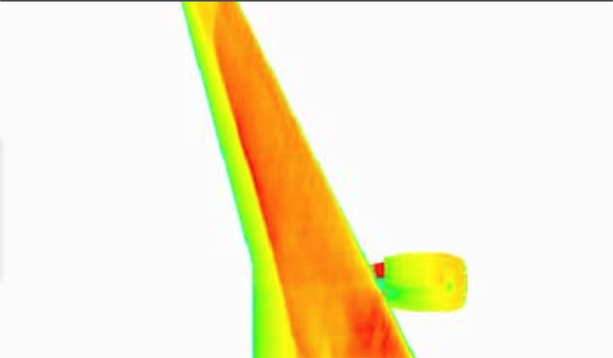
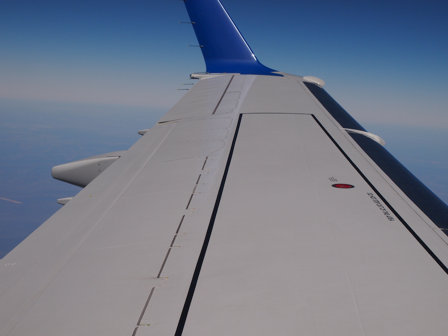
Your video shows a 738 or similar wing in transonic flight, the aircraft is at about M0.785 to M0.795, and has an aoa of around 2.3-2.5. In front of the shock, the flow is turbulent, behind the shock it has a layer of separated flow extending rearwards from the shock boundary layer foot. Not sure hat your point is. Any laminar flow on that wing has stopped on the left hand side, at, or before the flow got to the aft facing step of the slat on the wing. Oddly enough, for the last 5 years of testing the B737 in transonic drag reduction related to this very matter, we have seen various configurations that gave considerable drag reduction. Conventionally, a slat is expected to add 1% to total drag, however that neglects the step effect.
the following image is post flight from NASA on a LR31 test using sublimating chemicals to undertake visualisation of transition. Quoniam res ipsa loquitur. hot wire anemometry etc has often been used to detect transition, however we have found that such methods alter the experiment, as they introduce boundary trips to the experiment.
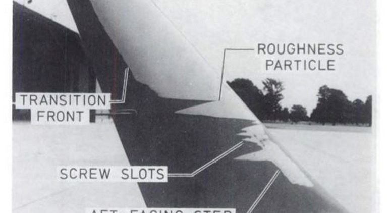
Is the photo succinct enough?
P.S.
the shockwave on the video is forward of that modelled by the manufacturer in their CFD. Just one of those things of modelling a monolithic meshed section that is simplified in order to attain rational CPU hours. It also exhibits instability, which arises from the shedding of the flow structure immediately behind the slat TE, and that happens about 10x more frequently than the vibration frequency of the shock as imaged. The shock motion does not correlate to engine vibration, or to the acoustic impingement on the bottom of the wing, which was an area of some research in the past by NASA and OEM's. BTW, the shock is observed at the point where the flow decelerates to subsonic, everything to the left of that with the exception of the separation area immediately behind the slat step is sonic, with the exception of the Kutta point which has zero velocity.
Most if not all 3D semi span models do not incorporate the slat as built, which gives a step in a critical part of the airfoil, The neatest example was the EMB170 wing CFD which shows a SC02 type pressure pattern, with a shock location around 0.8c, yet the same conditions in flight video the shock at 0.35-0.4c. The CFD had no slat... The difference in section drag count in detail testing is on the order of 25%-28% optimistic to that with a slat, a solution that tied up my own supercomputer for months to get, and took out the resources of the software supplier to run for a substantial time and cost.
The B737 wing is transonic in cruise, unless at very light weights, low mach, and or low altitude, as most transport aircraft are, by memory, above around M0.745 you will achieve Mcrit on the BAC section at average weights for altitude. Increase AOA, and the speed reduces to achieve Mcrit... and v.v.
Details matter.
Last edited by fdr; 27th Jun 2019 at 06:09.
As the muppets song goes: "...one of these things is not like the other...." Note the CFD doesn't have a slat... the wing does... There is negligible laminar flow on that wing, and none at all aft of the slat without some assistance like the device I developed, and even then, it is not laminar, it is hybrid.
About 15 years ago, when I was still flying PG and NG 737’s, we had a de-icing procedure that required us to place the stabilizer full nose down.
Including using the trim wheels, all the way to the stop.
It was said that this was necessary, so that the de-icing fluid could run down the aft end of the horizontal tail structure.
This procedure was abandoned later, and repaced by a neutral stab trim setting. So that fluid would not accumulate between the stabilizer and elevator, and subsequently freeze up during flight, impairing elevator authority.
Why am I telling you guys this? Well...
Very often, as I placed the stab trim full nose down with the trim wheel, the following would regularly happen.
It regularly was VERY hard to return the stab trim. INCLUDING using the trim wheels. You had to yank and pull the trim wheels quite a few times so that they would snap free, and the it was usable again and trimmable.
And this was at the gate/de-icing platform. Airspeed was zero.
If this “snap free” hardware problem turns out to be the issue here, than...Boeing is in for a hardware modification. That requires a totally new certification.
I suspect the MCAS is capable of driving the trim wheels all the way forward and capable of causing this same “snap free” lockup as I experinced regularly at the gate.
Join Date: Jan 2013
Location: UK
Age: 63
Posts: 37
Likes: 0
Received 0 Likes
on
0 Posts
Most engineers that designed embedded control systems in the 80's and afterwards were weaned on the PDP11 or other DEC machines that used memory-mapped I/O and included it in their designs. Motorola used it on the 6800 and Intel were the ones that promoted separate I/O instructions. Nowadays most control systems use memory-mapped I/O. So as soon as machines were developed that had memory addressing, I/O could not be access in user mode. Maybe memory-mapped I/O was the majority of designs for technical reasons, but I think the fact that you had to buy a $10,000 workstation to develop for the 8008.8080, and Motorola gave away kits of parts for engineers to build and write code on a cross-assembler on their department PDP11 went a long way to giving memory-mapped addressing the edge that it now enjoys.
On any system which has the concept of multiple users with different access levels and measures to isolate different users from accessing resources they were not authorised access to I/O was necessarily restricted. In systems with dedicated I/O this meant special faciltiies to manage access to I/O use, with memory mapped I/O this is provided as part of a wider memory management function. This is in fact another advantage of memory mapped I/O the unification of control of access to memory with control of access to I/O.
The level of detail discussed is completely irrelevant to the forum both approaches can work and it is not paticularily significant or relevant when considering the overall architecture of a safety related system.
What about just publishing the 737 MAX's flight test data? Everybody could see what exactly MCAS is needed for and whether to accept this or not?
The poor old processor got overloaded by data came from various sources? I think I posted somewhere that the new routine(s) associated with the MCAS data could overwhelm the control system from time to time, especially during the failure mode [i.e. vane's malfunction].
A series of simulator flights to test new software developed by Boeing revealed the flaw, according to one of the sources...
...In simulator tests, government pilots discovered that a microprocessor failure could push the nose of the plane toward the ground. It is not known whether the microprocessor played a role in either crash.
When testing the potential failure of the microprocessor in the simulators, "it was difficult for the test pilots to recover in a matter of seconds," one of the sources said. "And if you can't recover in a matter of seconds, that's an unreasonable risk.".
Boeing engineers are now trying to address the issue, which has led to another delay in recertifying the 737 Max...
===========
- https://edition.cnn.com/2019/06/26/p...law/index.html
New flaw discovered on Boeing 737 Max, sources say
...A new flaw has been discovered in the computer system for the Boeing 737 Max that could push the plane downward, according to two sources familiar with the testing, an issue that is expected to further delay the aircraft's return to service.A series of simulator flights to test new software developed by Boeing revealed the flaw, according to one of the sources...
...In simulator tests, government pilots discovered that a microprocessor failure could push the nose of the plane toward the ground. It is not known whether the microprocessor played a role in either crash.
When testing the potential failure of the microprocessor in the simulators, "it was difficult for the test pilots to recover in a matter of seconds," one of the sources said. "And if you can't recover in a matter of seconds, that's an unreasonable risk.".
Boeing engineers are now trying to address the issue, which has led to another delay in recertifying the 737 Max...
===========
- https://edition.cnn.com/2019/06/26/p...law/index.html
They have not even got in a real MAX yet, so what are we now looking at for flight testing 6 -12 months after the fix of the fix is presented?
Join Date: Oct 2018
Location: uk
Posts: 3
Likes: 0
Received 0 Likes
on
0 Posts
If an unidentified failure - cpu overload due to MCAS operations - leads to an unidentified fail state - uncontrollable operation of controls - is this a system operating as expectable since the designers havent designed the system properly?
Systems analysis requires identification of all reasonably foreseeable events, and 'computer operation overload', and the resultant fail state condition must surely be one of them.
Systems analysis requires identification of all reasonably foreseeable events, and 'computer operation overload', and the resultant fail state condition must surely be one of them.