


Category A PC1 or PC2

Thread Starter
Category A PC1 or PC2
Hello everybody,
I would like to discuss performance class 2 operations as compared to CAT A / PC1 operations on the S92.
If you are at MTOW (26.500lb), MSL, 1013, zero wind, 32°C, your TDP would be 47kt and you would be able to safe reject in 2.343ft (iFly precision) =)
And for the same conditions you will have to limit your take off mass as temperature goes above 32°C.
But if we use the chart for PC2:
MAXIMUM TAKEOFF AND LANDING GROSS WEIGHT
BASED ON 150 FPM OEI CLIMB AT 1000 FT ABOVE THE TAKEOFF SURFACE
CT7−8A MAXIMUM CONTINUOUS OEI POWER BEST ROC SPEED
We have a limitation that starts from 34°C.
Does anyone knows the reason for this difference?
If we are taking off from a paved clear runway shouldn´t those two be the same?
Best regards,
Vidual

I’m not close to my copy of the graphs, but the logical explanation is that in the PC1 case you are limited buy the first segment climb requirements (100 ft/min at Vtoss, L/G down and 2 min OEI power from 35-200 ft), so you will actually achieve greater than 150 ft/min in the second segment (Vy, L/G up, OEI CT from 200-1000 ft).
In the second example, you may achieve the PC2 requirement but would not achieve the first segment PC1 requirements.
If you check the graphs it should confirm this.
In the second example, you may achieve the PC2 requirement but would not achieve the first segment PC1 requirements.
If you check the graphs it should confirm this.
Thread Starter
Thank you for your reply,
I was thinking the same thing, but if you have enough power to comply with the second segment, shouldn’t this power be sufficient to comply with the first?
Do you think that has something about having hazards/damage to the aircraft if the failure occurs before TDP/DPATO?
I was thinking the same thing, but if you have enough power to comply with the second segment, shouldn’t this power be sufficient to comply with the first?
Do you think that has something about having hazards/damage to the aircraft if the failure occurs before TDP/DPATO?
To answer the first point, the drag is much higher in the first segment, as you are at a much lower speed and also the gear is down (I think the gear alone is worth a 50 ft/min penalty), so even though you have more power, the overall effect is that the RTOM is limited by the performance in that segment with lower Vtoss values. From memory, the demarcation point is Vtoss = 60 kias, when the second segment becomes limiting - which is logical because the Vtoss airspeed is closer to Vy.
I don't believe your second point is a factor - the rejected take off will never limit the RTOM in a runway take off profile (it will do in a helipad profile though).
Thread Starter
Sorry, I have a glitch and cannot see your reply unless I make this reply!
To answer the first point, the drag is much higher in the first segment, as you are at a much lower speed and also the gear is down (I think the gear alone is worth a 50 ft/min penalty), so even though you have more power, the overall effect is that the RTOM is limited by the performance in that segment with lower Vtoss values. From memory, the demarcation point is Vtoss = 60 kias, when the second segment becomes limiting - which is logical because the Vtoss airspeed is closer to Vy.
I don't believe your second point is a factor - the rejected take off will never limit the RTOM in a runway take off profile (it will do in a helipad profile though).
Suppose that appropriate Reject take off area will not be an issue.
We are using max TDP so we can have max payload for each flight, and still operating PC1 / CAT A
At these conditions, payload will have to be restricted if temperature goes above 32şC.
My point of view is that PC1 and PC2 should be the same for us. The only difference is that for PC1 you have to be able to safe reject and landing without any damaged to the aircraft, and for PC2 you could use unpaved areas that are not suitable for a reject landing but are for a SFL (safe force landing).
Last edited by alexandre.vidual; 28th May 2023 at 19:57. Reason: I have no permition to discuss offshore operation at this airport
You are mixing oranges and apples.
Firstly for PC1: the RFM explains the calculations for take-off mass and distance calculation for the CAT A procedure thus:
CATEGORY A HORIZONTAL TAKEOFF DISTANCE
The Category A horizontal takeoff procedure shown diagrammatically in Figure 4-7 features variable Takeoff Decision Points (TDP) and Takeoff Safety Speeds (Vtoss). The TDP, expressed only in terms of airspeed, is selectable in 1 knot increments between 30 and 48 knots. Vtoss is TDP + 15 knots. This permits payload to be traded off against available field length in such a manner that Category 9A9 one engine inoperative (OEI) climb performance minima can be maintained over a wide range of environmental conditions.
Figure 4-8 shows the Rejected Takeoff (RTO) and Continued Takeoff (CTO) distances as a function of pressure altitude, temperature, TDP speed, and headwind component. RTO and CTO distances are directly proportional to TDP speed, therefore lower TDP speeds equate to shorter field lengths. Figure 4-9 shows the maximum takeoff and landing gross weight as a function of pressure altitude, temperature, and TDP speed. Maximum takeoff and landing gross weight is also directly proportional to TDP speed, therefore higher TDP speeds equate to higher maximum takeoff gross weights.
The Category A takeoff procedure provides the flexibility to address specific payload and/or field length requirements appropriate to either of the following operational scenarios:
The graphs are produced from extensive flight testing and represent those dimensions that can be achieved by the average pilot with an aircraft that meets the minimum performance standard. The provision of those graphs is a complex process and provides the best operational data within the certification criteria.
For PC2 the calculation is less complex: for certification purposes the reject does not need to considered so (for example) the aircraft can be flown directly to Vy and thence into the climb. The PC2 imiting mass will the governed by: the maximum Certificated take-off mass; the environmental conditions; and the ability to achieve a ROC of 150ft/min at 1,000ft above the take-off surface.
There is no simple answer to you question as the limiting temperature/mass for PC1 might be one of a number of those mentioned in the RFM description.
The flight test engineer who produced those graphs lurks around the board; he might intervene and discuss this with you (as he has done with me in the past).
Jim
Firstly for PC1: the RFM explains the calculations for take-off mass and distance calculation for the CAT A procedure thus:
CATEGORY A HORIZONTAL TAKEOFF DISTANCE
The Category A horizontal takeoff procedure shown diagrammatically in Figure 4-7 features variable Takeoff Decision Points (TDP) and Takeoff Safety Speeds (Vtoss). The TDP, expressed only in terms of airspeed, is selectable in 1 knot increments between 30 and 48 knots. Vtoss is TDP + 15 knots. This permits payload to be traded off against available field length in such a manner that Category 9A9 one engine inoperative (OEI) climb performance minima can be maintained over a wide range of environmental conditions.
Figure 4-8 shows the Rejected Takeoff (RTO) and Continued Takeoff (CTO) distances as a function of pressure altitude, temperature, TDP speed, and headwind component. RTO and CTO distances are directly proportional to TDP speed, therefore lower TDP speeds equate to shorter field lengths. Figure 4-9 shows the maximum takeoff and landing gross weight as a function of pressure altitude, temperature, and TDP speed. Maximum takeoff and landing gross weight is also directly proportional to TDP speed, therefore higher TDP speeds equate to higher maximum takeoff gross weights.
The Category A takeoff procedure provides the flexibility to address specific payload and/or field length requirements appropriate to either of the following operational scenarios:
- Determine the maximum takeoff gross weight, given the available field length.
- Determine the required field length, given the desired mission takeoff gross weight.
The graphs are produced from extensive flight testing and represent those dimensions that can be achieved by the average pilot with an aircraft that meets the minimum performance standard. The provision of those graphs is a complex process and provides the best operational data within the certification criteria.
For PC2 the calculation is less complex: for certification purposes the reject does not need to considered so (for example) the aircraft can be flown directly to Vy and thence into the climb. The PC2 imiting mass will the governed by: the maximum Certificated take-off mass; the environmental conditions; and the ability to achieve a ROC of 150ft/min at 1,000ft above the take-off surface.
There is no simple answer to you question as the limiting temperature/mass for PC1 might be one of a number of those mentioned in the RFM description.
The flight test engineer who produced those graphs lurks around the board; he might intervene and discuss this with you (as he has done with me in the past).
Jim
Join Date: Mar 2010
Location: North America
Posts: 107
Likes: 0
Received 0 Likes
on
0 Posts
As JimL correctly stated, you are mixing oranges (PC1) and apples (PC2). The OEI climb performance Certification requirements are different. As 212man explained, PC2 has no first segment OEI climb requirement, so you may be able to achieve the PC2 second segment requirement at a WAT condition for which you would not be able to achieve the PC1 first segment requirement. The PC1 chart is essentially constructed by superimposing the first segment chart on top of the second segment chart and plotting the most restrictive in terms of allowable gross weight for all combinations of altitude and temperature.
I believe that you must declare whether you are operating in PC1 or PC2. If you declare that you are operating in PC1, even if you have an infinite length runway, you must use the PC1 chart.
I believe that you must declare whether you are operating in PC1 or PC2. If you declare that you are operating in PC1, even if you have an infinite length runway, you must use the PC1 chart.
Thread Starter
Guys,
I pretty sure that I know the differences between PC1 and PC2 operations. Maybe my English are not good enough to explain what I want to know…
Simple question:
If I have just enough power to climb at 150ft/min OEI MCP from 0ft to 1000ft with Vy L/G retracted, will I or will I not have sufficient power to climb from 0ft to 200ft at 2 min power, L/G extended at VTOSS? Suppose that you are using MAX VTOSS
alexandre.vidual:
The answer to your question can be found in the RFM which contains take-off WAT, the first segment (Figure 4-10) and second segment (Figure 4-11) graphs - you should be more familiar with those than me. As heliTester has said:
By chosing your test conditions and then examining the relevant graphs, your limiting case will be revealed (I have never flown the S92 so I am not as familiar with the RFM as you might (should) be). However, there are some general points that emerge from this discussion that might be worth considering.
The S92 RFM provides a trade off between the restricted take-off mass and the length of the reject area. The acceleration to the defined (but variable) Vtoss is protected (in the sense of meeting the PC1 conditions of 'safe landing' or 'safe continued flight') by the length of the reject area. As the speed increases: the required rejected area increases; but the ability to climb improves - up to Vy from where it then decreases.
However, none of this exists in isolation; the objective of providing the Category A procedure is to allow the pilot/aicraft to stay within the limitations of the heliport which include: the rejected take-off area available, the take-off distance available and the Obstacle Limitation Surfaces (OLSs). The take-off OLS emanates from the end of the FATO (rejected take-off area) or the clearway.
With a PC2 heliport, there is effectively no requirement for a rejected take-off area (which permits a safe landing - i.e. one that does not result in an unservicable aircraft); however, there is a requirement for a surface which permits a safe-forced-landing (one for which the probability of no injury to the occupants is high). Providing that the SFL area (which is in effect a clearway) is sufficiently large enough, the aircraft can accelerate to Vy before rotating to the climb.
The provision of the surfaces at the PC1 heliport is the responsibility of the heliport owner. The responsibility for defining the SFL area rests with the operator/pilot. There is no defined first climb segment for PC2 (but the Category A graph could be considered).
For PC2 the helicopter remains within the limitation of the RFM for Category A when more than 9 passengers are carried by 1. applying the maximum mass; 2. staying within the limitation of the HV diagram, and; 3. meeting the conditions for the second segment climb. A number of RFMs provide a basic Category A WAT which satisfies the conditions of 1 and 3.
The requirement to apply the PC1 or PC2 operational limitations rests with the Authority (as in the State's regulations or the Operators OM).
Some other observations that are not confined to the S92:
During recent work to establish suitable obstacle limitation surfaces for PC 1 vertical procedures, it has been noted that almost all small and medium twins (which may apply to the super-mediums) have a better first segment climb performance than second (sometimes in excess of 500ft/min, this results from the improved 2.5 minute (30 seconds plus 2 minutes or just 2.5 minutes) power output).
The largest problem with the Category A procedures is the level acceleration segment at 200ft (from Vtoss to Vy) which halts the climb and, in a number of cases, drives the helicopter into the take-off OLS. However, these small and medium twins have the ability with a power-unit failure at TDP, to reach 1000ft within the 2.5 minutes. Manufacturers have become aware of this and are now providing modified profiles that do not require a level climb at 200 ft above the take-off point (or the TDP when that is in excess of 200 ft).
This has a knock-on effect for PC2 where the application of the 2.5 minute power can provide a healthy reserve should a power-unit fail soon after take-off; however, unless a defined profile is flown (and the graphs applied), it is not clear how that will impact upon the obstacle clearance ability.
Mods please note: This is a wider subject than the S92 in Brazil and perhaps the title of the thread should be modified to signify this.
I'll pause now for others to comment but will continue if there are any questions.
The answer to your question can be found in the RFM which contains take-off WAT, the first segment (Figure 4-10) and second segment (Figure 4-11) graphs - you should be more familiar with those than me. As heliTester has said:
The PC1 chart is essentially constructed by superimposing the first segment chart on top of the second segment chart and plotting the most restrictive in terms of allowable gross weight for all combinations of altitude and temperature
The S92 RFM provides a trade off between the restricted take-off mass and the length of the reject area. The acceleration to the defined (but variable) Vtoss is protected (in the sense of meeting the PC1 conditions of 'safe landing' or 'safe continued flight') by the length of the reject area. As the speed increases: the required rejected area increases; but the ability to climb improves - up to Vy from where it then decreases.
However, none of this exists in isolation; the objective of providing the Category A procedure is to allow the pilot/aicraft to stay within the limitations of the heliport which include: the rejected take-off area available, the take-off distance available and the Obstacle Limitation Surfaces (OLSs). The take-off OLS emanates from the end of the FATO (rejected take-off area) or the clearway.
With a PC2 heliport, there is effectively no requirement for a rejected take-off area (which permits a safe landing - i.e. one that does not result in an unservicable aircraft); however, there is a requirement for a surface which permits a safe-forced-landing (one for which the probability of no injury to the occupants is high). Providing that the SFL area (which is in effect a clearway) is sufficiently large enough, the aircraft can accelerate to Vy before rotating to the climb.
The provision of the surfaces at the PC1 heliport is the responsibility of the heliport owner. The responsibility for defining the SFL area rests with the operator/pilot. There is no defined first climb segment for PC2 (but the Category A graph could be considered).
For PC2 the helicopter remains within the limitation of the RFM for Category A when more than 9 passengers are carried by 1. applying the maximum mass; 2. staying within the limitation of the HV diagram, and; 3. meeting the conditions for the second segment climb. A number of RFMs provide a basic Category A WAT which satisfies the conditions of 1 and 3.
The requirement to apply the PC1 or PC2 operational limitations rests with the Authority (as in the State's regulations or the Operators OM).
Some other observations that are not confined to the S92:
During recent work to establish suitable obstacle limitation surfaces for PC 1 vertical procedures, it has been noted that almost all small and medium twins (which may apply to the super-mediums) have a better first segment climb performance than second (sometimes in excess of 500ft/min, this results from the improved 2.5 minute (30 seconds plus 2 minutes or just 2.5 minutes) power output).
The largest problem with the Category A procedures is the level acceleration segment at 200ft (from Vtoss to Vy) which halts the climb and, in a number of cases, drives the helicopter into the take-off OLS. However, these small and medium twins have the ability with a power-unit failure at TDP, to reach 1000ft within the 2.5 minutes. Manufacturers have become aware of this and are now providing modified profiles that do not require a level climb at 200 ft above the take-off point (or the TDP when that is in excess of 200 ft).
This has a knock-on effect for PC2 where the application of the 2.5 minute power can provide a healthy reserve should a power-unit fail soon after take-off; however, unless a defined profile is flown (and the graphs applied), it is not clear how that will impact upon the obstacle clearance ability.
Mods please note: This is a wider subject than the S92 in Brazil and perhaps the title of the thread should be modified to signify this.
I'll pause now for others to comment but will continue if there are any questions.
Alexandre raised some. very good questions in his original post and with his indulgence the resulting discussion will be very useful to all of us in gaining a better understanding of the many issues at play in how the profiles are determined and not just for the S-92 but for other aircraft as well.

Thread Starter
Some great material about the subject:
aerosociety.com/media/11827/simon-harlow.pdf
1drv.ms/f/s!AvaOt4hw6Yivg8ZlyT8TzJga4hccdw?e=qIfL3x
I´m not alowed to put links yet, so you should insert www infront of those links...
Best regards,
Vidual
1drv.ms/f/s!AvaOt4hw6Yivg8ZlyT8TzJga4hccdw?e=qIfL3x
I´m not alowed to put links yet, so you should insert www infront of those links...
Best regards,
Vidual
Last edited by alexandre.vidual; 1st Jun 2023 at 13:41. Reason: adjusting links
Join Date: Mar 2010
Location: North America
Posts: 107
Likes: 0
Received 0 Likes
on
0 Posts
Simple question:
If I have just enough power to climb at 150ft/min OEI MCP from 0ft to 1000ft with Vy L/G retracted, will I or will I not have sufficient power to climb from 0ft to 200ft at 2 min power, L/G extended at VTOSS? Suppose that you are using MAX VTOSS
If I have just enough power to climb at 150ft/min OEI MCP from 0ft to 1000ft with Vy L/G retracted, will I or will I not have sufficient power to climb from 0ft to 200ft at 2 min power, L/G extended at VTOSS? Suppose that you are using MAX VTOSS
Thread Starter
I did, but I can´t post here because I don´t have 8 replys yet...
So if you want to take a look into it you can go to this link, there are 4 images.
1drv.ms/f/s!AvaOt4hw6Yivg8ZlyT8TzJga4hccdw?e=TILS0V
am I missing something? Why the 2°C difference?
Best regards,
Vidual
So if you want to take a look into it you can go to this link, there are 4 images.
1drv.ms/f/s!AvaOt4hw6Yivg8ZlyT8TzJga4hccdw?e=TILS0V
am I missing something? Why the 2°C difference?
Best regards,
Vidual
Last edited by alexandre.vidual; 1st Jun 2023 at 13:40. Reason: adjusting links
Join Date: Mar 2010
Location: North America
Posts: 107
Likes: 0
Received 0 Likes
on
0 Posts
alexandre.vidual,
Extrapolating the PC1 chart shows that increasing the TDP/Vtoss by 1-kt (above the limit) would produce 26,500 lb at sea level 34˚C, but you obviously can’t exceed the TDP/Vtoss limit. I think the 2˚C difference is between the PC1 chart and the first segment climb chart, and I assume that is a function of nomogram format chart and graphical interpolation precision.
HT
The link Alexandre points to in his penultimate post show Dino Paggi explaining the Leonardo solution to the problem mentioned above:
Aibus have chosen a different solution of a more limited nature as those who fly the AH145 will note; Bell have provided an alternative for the B429.
As Dino points out in his very clear presentation, it is not just the basic limitations (first and second segment climb) that have to be applied, the profile has to be adapted to address the obstacle environment of the heliport. This is more of an issue with helipad or short field heliports than runway-type sites.
For most heliports the take-off OLS starts at the end of the rejected take-off area (usually the FATO - which may be no larger than 1.5D); at the inner edge of the take-off OLS the helicopter must at 35ft and have met the requirement of the take-off distance required (TODRH - i.e. Vtoss and positive rate of climb). Dino does not consider this in his presentation - showing a marker at 35ft on the departure curve or, in a later slide, as being over a clear surface.
In Dinos's slides, all of the area below the helicopter up to the point that TODRH is reached is actually a clearway - declared by the heliport, or not (a virtual clearway). A clearway permits the convertion of potential energy (the height at the TDP) to kinetic energy (speed of the helicopter) by descending and accelerating to the TODRH. What is provided by the manufactuers in their performance data, is the distance to the TODRH (from the TDP or back of the FATO) and the drop-down (from the TDP to the min-dip - shown on Dino's slide as 15ft above the surface) but not the distance of the min-dip from either of the two reference points; the PC1 take-off OLS (slope from the end of the FATO/clearway) is not considered. (In the manufacturers world, the surface is regarded as flat but with obstacles.)
For the heliport designer, increasing the PC1 take-off OLS to greater than the current 4.5% (approximately 2.57 degrees) to clear obstacles is not really an option; neither is providing an obstacle free clearway on the surface. The solution is to elevate the origin of the OLS to a point where it clears all obstacles along its length (which may be curved) and provide a virtual clearway. This clearway, of a distance required by the design helicopter, commences directly above the outer edge of the FATO/rejected take-off area and intercepts the (elevated) OLS at the required distance. The origin of the take-off surface is then regarded as being displaced to the outer edge of the clearway at the height of the clearway. The details of the clearway - its height and length, and the origin of the take-off OLS should be promulgated in the heliport data.
The pilot now knows the height of the surface (the clearway) above which the TDP has to be provided (so the distance to the mon-dip is not an issue) and the distance to the take-off distance available (the commencement of the, displaced, take-off surface).
This solution is not just confined to the heliport designer, it also permits an operator to provide similar data at any heliport to which operations are considered (for example a heliport at a hospital). To avoid unecessary calculations, a virtual clearway of 300m could be used; most helicopter will be able to use this. As the height of the TDP increases, the required clearway distance decreases (unless the vertical procedure is a true vertical one i.e. as for the AH145, for which it remains constant).
The gist of this can be seen in the following presentation that uses the relocation of Addenbrookes helipad as an example.
https://www.dropbox.com/s/i5am5zyg5a...sion.pptx?dl=0
It is a pity that Alexandre has reached his temporary limit of seven posts; however, deleting the thread is not the solution to this as it negates the contribution of others.
The largest problem with the Category A procedures is the level acceleration segment at 200ft (from Vtoss to Vy) which halts the climb and, in a number of cases, drives the helicopter into the take-off OLS. However, these small and medium twins have the ability with a power-unit failure at TDP, to reach 1000ft within the 2.5 minutes. Manufacturers have become aware of this and are now providing modified profiles that do not require a level climb at 200 ft above the take-off point (or the TDP when that is in excess of 200 ft).
As Dino points out in his very clear presentation, it is not just the basic limitations (first and second segment climb) that have to be applied, the profile has to be adapted to address the obstacle environment of the heliport. This is more of an issue with helipad or short field heliports than runway-type sites.
For most heliports the take-off OLS starts at the end of the rejected take-off area (usually the FATO - which may be no larger than 1.5D); at the inner edge of the take-off OLS the helicopter must at 35ft and have met the requirement of the take-off distance required (TODRH - i.e. Vtoss and positive rate of climb). Dino does not consider this in his presentation - showing a marker at 35ft on the departure curve or, in a later slide, as being over a clear surface.
In Dinos's slides, all of the area below the helicopter up to the point that TODRH is reached is actually a clearway - declared by the heliport, or not (a virtual clearway). A clearway permits the convertion of potential energy (the height at the TDP) to kinetic energy (speed of the helicopter) by descending and accelerating to the TODRH. What is provided by the manufactuers in their performance data, is the distance to the TODRH (from the TDP or back of the FATO) and the drop-down (from the TDP to the min-dip - shown on Dino's slide as 15ft above the surface) but not the distance of the min-dip from either of the two reference points; the PC1 take-off OLS (slope from the end of the FATO/clearway) is not considered. (In the manufacturers world, the surface is regarded as flat but with obstacles.)
For the heliport designer, increasing the PC1 take-off OLS to greater than the current 4.5% (approximately 2.57 degrees) to clear obstacles is not really an option; neither is providing an obstacle free clearway on the surface. The solution is to elevate the origin of the OLS to a point where it clears all obstacles along its length (which may be curved) and provide a virtual clearway. This clearway, of a distance required by the design helicopter, commences directly above the outer edge of the FATO/rejected take-off area and intercepts the (elevated) OLS at the required distance. The origin of the take-off surface is then regarded as being displaced to the outer edge of the clearway at the height of the clearway. The details of the clearway - its height and length, and the origin of the take-off OLS should be promulgated in the heliport data.
The pilot now knows the height of the surface (the clearway) above which the TDP has to be provided (so the distance to the mon-dip is not an issue) and the distance to the take-off distance available (the commencement of the, displaced, take-off surface).
This solution is not just confined to the heliport designer, it also permits an operator to provide similar data at any heliport to which operations are considered (for example a heliport at a hospital). To avoid unecessary calculations, a virtual clearway of 300m could be used; most helicopter will be able to use this. As the height of the TDP increases, the required clearway distance decreases (unless the vertical procedure is a true vertical one i.e. as for the AH145, for which it remains constant).
The gist of this can be seen in the following presentation that uses the relocation of Addenbrookes helipad as an example.
https://www.dropbox.com/s/i5am5zyg5a...sion.pptx?dl=0
It is a pity that Alexandre has reached his temporary limit of seven posts; however, deleting the thread is not the solution to this as it negates the contribution of others.
Last edited by JimL; 29th May 2023 at 10:32. Reason: Adding of link to presentation.
Thread Starter
Thank you all for the excellent explanations and for sharing your knowledge with me.
I think my initial question has been answered.
But JimL, in a very illuminating way, added some excellent content that can still be widely discussed.
Vidual
I think my initial question has been answered.
But JimL, in a very illuminating way, added some excellent content that can still be widely discussed.
Vidual
Thread Starter
Another subject that we could mention is about operations to/from elevated helideck (oil rigs/vessels)
S92 RFM does not mention a defined CAT A procedure to elevated helidecks, instead you find this at part 2 supplemental performance:
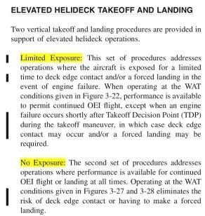
Should I consider "no expousure" as a CAT A procedure?
Best regards,
Vidual
S92 RFM does not mention a defined CAT A procedure to elevated helidecks, instead you find this at part 2 supplemental performance:
Should I consider "no expousure" as a CAT A procedure?
Best regards,
Vidual
Alexandre.Vidual
No, it is PC2.
There is a subtle difference to certification in Category A - which is what PC1 or PC2 is, and a Category A procedure - which satisfies the remainder of the requirements of Part 2 of the certification code - i.e. the seven take-off rules between 29.51 to 29.62 inclusive and the four landing rules of 29.75 to 29.81 inclusive.
How many single engine failures have occurred within the S-92 Fleet worldwide since that aircraft has been in service and what "rate" does that amount to in terms of engine failures per Take Off for the fleet?
Out of those engine failures how many occurred during Cat A Takeoff profiles and what was the outcome of those situations?
One Sikorsky Test Pilot once suggested that perhaps we as an industry placed too high an emphasis upon training for engine failures as modern engines had matured to having a very good rate between engine failiures.
Is this whole notion of Cat A PC1 and PC2 akin to that suggested by that Test Pilot?
Meaning....not really necessary and thus placing unnecessary burdens upon Operators?
I recall the difference in performance when the same aircraft had a pair of PT6-3 and a pair of PT6-6 Engines....and the performance of the aircraft was significantly improved by having the -6 Engines.
If we compare an aircraft with marginal single engine power as compared to an aircraft that is blessed with a very strong single engine....is there a genuine benefit to Class A over non-class A takeoff profiles?
Thread Starter
SASless,
5-Year Moving Window:
Sudden Power Loss per 100,000 Engine Flight Hours (Engine): 0.30
Sudden Power Loss per 100,000 Engine Flight Hours (Engine & Helicopter): 0.60
I agree with you. But we are having problems with our regulatory agency, which does not allow us to operate in performance classes, and obliges us to operate in CAT A for all take-offs and landings, land and sea. There are no code of performance here.
This greatly restricts the viability of the operation, increasing costs enormously. For us, as pilots, it would be great to always operate in PC1, but it is not always an option. Especially with older helicopters, short runways and high OAT.
As Simon Harlow states on his presantation: "Twin engine operations using 9 second exposure is 0.141% of the current accident risk. Are we looking in the right place?"
In the last 10 years I have been seen pilots approaching to helidecks in an "aggressive" way simply because of the fear of exposing themselves to an engine failure...
In my view, new rotorcrafts are having their engines dimensioned to reduce this risk and increase the capability to operate PC1. Is this really happening?
Best regards,
Vidual