


Helicopter down outside Leicester City Football Club

Join Date: Jan 2013
Location: Midlands
Posts: 136
Likes: 0
Received 0 Likes
on
0 Posts
Originally Posted by [email protected]
Pozidrive - The control rod is a hydraulic piston with attachments as hoistop and nodrama say.
The input arm acts on the servo pilot valve to direct hyd fluid to one side or other of that piston, thus moving the control rod in and out.
The reason for having the other end of the input arm connected to the control rod is to provide the follow-up action and recentralise the servo valve when the TR pitch has been driven to the required position.
Still no explanation of how the hydraulics act on the control shaft. Sectional drawing anyone?

Join Date: Jan 2013
Location: Midlands
Posts: 136
Likes: 0
Received 0 Likes
on
0 Posts
Fig. 4 in the bulletin appears to show sealed bearings. Seal shown in pink at the outer faces of the bearing.
Join Date: Jan 2013
Location: Midlands
Posts: 136
Likes: 0
Received 0 Likes
on
0 Posts
Crab no disrespect aimed at u or anyone else on here. This is the bit I am struggling to understand and why am asking the experts if it is a hydraulic piston with attachments on both ends how did it end up inside the outer shaft wouldn't it have to break/destroy the servo actuator?
Join Date: Jan 2013
Location: Midlands
Posts: 136
Likes: 0
Received 0 Likes
on
0 Posts
Pozidrive - picture it as a MR servojack, the moving part of the jack pushes upwards and pulls downwards on the swashplate and is a piston acted on directly by hydraulic pressure - the direction of travel is determined by which side of that piston the pilot valve/servo valve directs the pressure fluid.
It is a one piece element, fescalised to reduce wear and the TR servo jack (the control rod) is exactly the same.
It is a one piece element, fescalised to reduce wear and the TR servo jack (the control rod) is exactly the same.
Join Date: Mar 2007
Location: UK
Posts: 321
Likes: 0
Received 0 Likes
on
0 Posts
Pozidrive - "The control shaft passes through an outer shaft, which forms part of the tail rotor hydraulic actuator piston" is referring to the part of the servo (actuator) that is boxed in Fig 3, the RH part of that boxed area. They are referring to the internal workings of the servo (actuator).
'Control shaft' is the term that the AAIB have chosen to use. Shaft, rod, whatever - it's the same part.
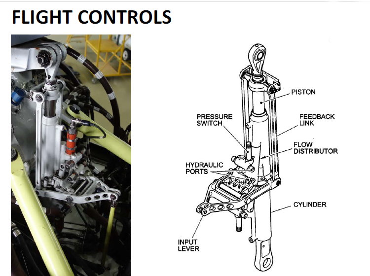
In Crabs diagrams below, your hollow, or outer shaft is the cylinder. In my earlier sketch drawing, it is the dotted line box in the servo.
'Control shaft' is the term that the AAIB have chosen to use. Shaft, rod, whatever - it's the same part.
In Crabs diagrams below, your hollow, or outer shaft is the cylinder. In my earlier sketch drawing, it is the dotted line box in the servo.
Last edited by nodrama; 13th Dec 2018 at 08:00.
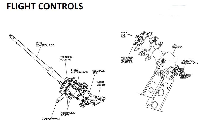
Tail Rotor Servo Jack
Main Rotor Servo Jack
Servo valve and piston
OAP
Join Date: Mar 2007
Location: UK
Posts: 321
Likes: 0
Received 0 Likes
on
0 Posts
For those who might be interested, I've compiled a 'tutorial' from another source that hopefully explains duplex bearing pre-load. The duplex bearing that is the subject of this thread is a 'back-to-back' paired bearing and it is the inner race that is pre-loaded. As Crab mentioned, pre-installation, the spider case is heated and the bearing frozen to enable an interference fit on the outer race. The inner race is then pre-loaded with the nut.
From another source- "One of the final steps in the bearing manufacturing process is the assembly of the individual bearing components: the outer ring, inner ring, balls and retainer (or ball separator). When the bearings are assembled, it is necessary to have a controlled amount of internal clearance, or looseness between the rings and balls. This is referred to as radial play in most bearing catalogs.
In certain applications, this internal clearance must be removed for a pair of bearings to operate properly. The application of an axial load across a pair of bearings – for the purpose of removing free internal clearances – is called preload.
Benefits of preloading ball bearings include:
If, under operating conditions, a bearing has radial play this means that one bearing race can be moved radially and axially relative to the other. With rotation, this looseness translates into wobble or non-repetitive runout. This motion is unacceptable in applications such as machine tool spindles, electric motors, optical encoders, flow meters, and high-speed hand tools.
The application of axial preload forces the balls into contact with raceways, establishing a contact angle which causes the ball set to rotate in a uniform circumferential plane.
Duplex bearings are matched pairs of bearings with “built-in” preload. The inner or outer ring faces have been ground to a precise dimension known as the preload offset. This offset corresponds to the rings axial movement when a specific axial preload is applied. When the bearings are clamped together at assembly the offset faces abut, establishing a permanent, rigid preload in the bearing set.
Duplex bearings have increased radial and axial rigidity. There are three common preload configurations. DB (back-to-back) and DF (face-to-face) can handle bi-directional thrust loads. DT (tandem) can handle very heavy unidirectional thrust loads. At higher speeds, these bearings can run hotter due to the rigid preload. These bearings are commonly used in machine tool and other spindle applications, due to their low deflection rate, minimal runout and ease of assembly.
How much preload should be applied?
In general, provided the design requirements are met, the least amount of preload is desired
What are the benefits of preload?
Rotational accuracy and precise shaft positioning, elimination or reduction of ball skidding, control and reduction of axial and radial deflection under applied load, noise reduction, load sharing between bearings
Does preload have any effect on a bearings operational life?
Bearing life decreases as preload is increased
What other side-effects of preload should I know about?
With increased or excessive preload, stresses are higher and excess heat is generated "
From another source- "One of the final steps in the bearing manufacturing process is the assembly of the individual bearing components: the outer ring, inner ring, balls and retainer (or ball separator). When the bearings are assembled, it is necessary to have a controlled amount of internal clearance, or looseness between the rings and balls. This is referred to as radial play in most bearing catalogs.
In certain applications, this internal clearance must be removed for a pair of bearings to operate properly. The application of an axial load across a pair of bearings – for the purpose of removing free internal clearances – is called preload.
Benefits of preloading ball bearings include:
- Rotational accuracy and precise shaft positioning
- Elimination or reduction of ball skidding
- Control and reduction of axial and radial deflection under applied load
- Noise reduction
- Load sharing between bearings
If, under operating conditions, a bearing has radial play this means that one bearing race can be moved radially and axially relative to the other. With rotation, this looseness translates into wobble or non-repetitive runout. This motion is unacceptable in applications such as machine tool spindles, electric motors, optical encoders, flow meters, and high-speed hand tools.
The application of axial preload forces the balls into contact with raceways, establishing a contact angle which causes the ball set to rotate in a uniform circumferential plane.
Duplex bearings are matched pairs of bearings with “built-in” preload. The inner or outer ring faces have been ground to a precise dimension known as the preload offset. This offset corresponds to the rings axial movement when a specific axial preload is applied. When the bearings are clamped together at assembly the offset faces abut, establishing a permanent, rigid preload in the bearing set.
Duplex bearings have increased radial and axial rigidity. There are three common preload configurations. DB (back-to-back) and DF (face-to-face) can handle bi-directional thrust loads. DT (tandem) can handle very heavy unidirectional thrust loads. At higher speeds, these bearings can run hotter due to the rigid preload. These bearings are commonly used in machine tool and other spindle applications, due to their low deflection rate, minimal runout and ease of assembly.
How much preload should be applied?
In general, provided the design requirements are met, the least amount of preload is desired
What are the benefits of preload?
Rotational accuracy and precise shaft positioning, elimination or reduction of ball skidding, control and reduction of axial and radial deflection under applied load, noise reduction, load sharing between bearings
Does preload have any effect on a bearings operational life?
Bearing life decreases as preload is increased
What other side-effects of preload should I know about?
With increased or excessive preload, stresses are higher and excess heat is generated "

Join Date: Jan 2013
Location: Midlands
Posts: 136
Likes: 0
Received 0 Likes
on
0 Posts
Pozidrive - "The control shaft passes through an outer shaft, which forms part of the tail rotor hydraulic actuator piston" is referring to the part of the servo (actuator) that is boxed in Fig 3, the RH part of that boxed area. They are referring to the internal workings of the servo (actuator).
'Control shaft' is the term that the AAIB have chosen to use. Shaft, rod, whatever - it's the same part.
In Crabs diagrams below, your hollow, or outer shaft is the cylinder. In my earlier sketch drawing, it is the dotted line box in the servo.
'Control shaft' is the term that the AAIB have chosen to use. Shaft, rod, whatever - it's the same part.
In Crabs diagrams below, your hollow, or outer shaft is the cylinder. In my earlier sketch drawing, it is the dotted line box in the servo.
"The control shaft passes through an outer shaft which forms part of the hydraulic actuator piston" If that description is correct there must be more than one component, and the control shaft is not the piston.
Nodrama - great post, very informative  Thank you.
Pozidrive - I think you are getting too hung up on the wording in the report. My diagrams are of a 139 TR setup which is near identical.
if you replace the word 'which' with the word 'and' then it might make it clearer.
Thank you.Pozidrive - I think you are getting too hung up on the wording in the report. My diagrams are of a 139 TR setup which is near identical.
if you replace the word 'which' with the word 'and' then it might make it clearer.
For instance: EC-135 has practically no grease lubricating requirement anywhere on airframe, as it was a goal of designer to make it low maintenance as much as possible. Swashplate bearing is still regularly grease lubricated with grease gun (comes about once a year/400FH)
Just a side note: A109Power had originally T/R duplex bearing grease lubrication schedule every 600hours or 24 months. To put grease in, the whole assembly had to be removed and disassembled to access the bearing (including removal of Tail rotor, as duplex bearing is "around" T/R driveshaft, connected with set of levers and scissors - entirelly different design than AW169)
Then in 2009 a mandatory SB came, requiring change of bearing housing to one with grease nipple and lubrication interval shortened to 100 hours / 6 months.
nodrama, many thanks for clarifying duplex bearing to everyone - nice piece of machinery engineering knowledge.
I still do not know, how exactly the control shaft and hydraulic power are interacting on T/R servo of AW169

nodrama,
"Duplex bearings are matched pairs of bearings with “built-in” preload. The inner or outer ring faces have been ground to a precise dimension known as the preload offset. This offset corresponds to the rings axial movement when a specific axial preload is applied. When the bearings are clamped together at assembly the offset faces abut, establishing a permanent, rigid preload in the bearing set"
I think that this quote from your tutorial is probably the important bit. IMO, the "preload" in this case is the achievement of the design running clearance and this is mainly done by the machining process. Where your tutorial refers to preload, I believe that it means precisely this, the amount of bearing clearance (or interference) when the assembly is clamped together, achieved through the machined dimensions of the components. Yes, the assembly will come with a design clamping load or torque setting to achieve and maintain the integrity of the assembly in use.
Where your tutorial goes on to say these comments:
"How much preload should be applied?
In general, provided the design requirements are met, the least amount of preload is desired
What are the benefits of preload?
Rotational accuracy and precise shaft positioning, elimination or reduction of ball skidding, control and reduction of axial and radial deflection under applied load, noise reduction, load sharing between bearings
Does preload have any effect on a bearings operational life?
Bearing life decreases as preload is increased
What other side-effects of preload should I know about?
With increased or excessive preload, stresses are higher and excess heat is generated "
Again, these refer to the machined-in preload, not the amount that the retaining nut is tightened. Obviously, the installation / assembly instructions for the components will be specific.
OAP
I still do not know, how exactly the control shaft and hydraulic power are interacting on T/R servo of AW169
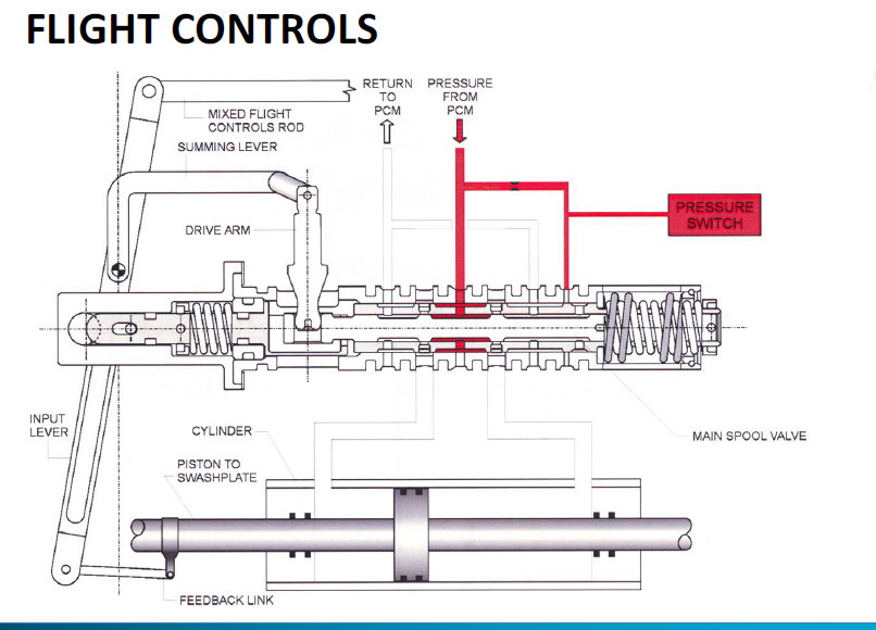
The input lever from the yaw controls moves the pilot/spool valve which allows hyd pressure to one side or other of the piston - that piston is part of the control rod.
The feedback link stops the spool valve directing fluid once the piston has moved in the appropriate direction.
It is that feedback link that came undone on the 189 meaning that the follow up action was removed and the piston did what the spool valve asked it to do - and it kept motoring until it reached full travel.
Join Date: Mar 2007
Location: UK
Posts: 321
Likes: 0
Received 0 Likes
on
0 Posts
OAP - you may be correct? It is still possible to relate this sentence ......
"The inner or outer ring faces have been ground to a precise dimension known as the preload offset. This offset corresponds to the rings axial movement when a specific axial preload is applied. When the bearings are clamped together at assembly the offset faces abut, establishing a permanent, rigid preload in the bearing set." ...
..... to the image I posted at #1105 to understand how torquing the nut effects the Duplex bearing.
And maybe this sentence.....
"Duplex bearings are matched pairs of bearings with “built-in” preload"
......should finish "built-in preload offset".
Last edited by nodrama; 13th Dec 2018 at 14:58. Reason: spelling
Avoid imitations
Join Date: Nov 2000
Location: Wandering the FIR and cyberspace often at highly unsociable times
Posts: 14,573
Received 415 Likes
on
218 Posts
I think if you look very carefully, you will see in that diagram that the outer races are made with a deeper track on their inside faces so that they can carry a greater axial load in one direction. The diagram does show that it is designed to carry equal load in each direction but, offset. Obviously, there are a huge variety of options that suit different applications. I believe that the "preload" term may be something of a misnomer. The manufacturing tolerances are designed so that as the inner races are clamped, and move together, the clearances of the balls in their races are positioned where they are designed to run so, this part of the process is one of correctly positioning the bearing components. Also worth noting that, unless the parts are Murphy proof, the component bearings might be assembled in wrong order(s), with their characteristics corrupted. Depending upon the method of clamping and holding the inner races, the required torque load on the retaining nut will also be defined and this will be part of the overall design.
OAP
OAP
Pozidrive - "The control shaft passes through an outer shaft, which forms part of the tail rotor hydraulic actuator piston" is referring to the part of the servo (actuator) that is boxed in Fig 3, the RH part of that boxed area. They are referring to the internal workings of the servo (actuator).
'Control shaft' is the term that the AAIB have chosen to use. Shaft, rod, whatever - it's the same part.
In Crabs diagrams below, your hollow, or outer shaft is the cylinder. In my earlier sketch drawing, it is the dotted line box in the servo.
'Control shaft' is the term that the AAIB have chosen to use. Shaft, rod, whatever - it's the same part.
In Crabs diagrams below, your hollow, or outer shaft is the cylinder. In my earlier sketch drawing, it is the dotted line box in the servo.
 , many thanks nodrama for your professionalism and to crabs for the diagrams