


Main Rotor Blade Chordwise CG?

Thread Starter
Join Date: Aug 2006
Location: California
Posts: 78
Likes: 0
Received 0 Likes
on
0 Posts
Main Rotor Blade Chordwise CG?
I'm looking for information on chordwise CG of the NACA 23012 airfoil. The texts I've read state that blade stability is achieved when the balance is at 25% from the leading edge. Is there a range over which there is stability or is 25% the rule, even with a semi-symmetrical airfoil.
Mike
Mike

Our stability rule at Bell Helicopter (1978-2008 rotor structural analysis) was to have the C.G. in front of quarter chord. Sometimes it took concentrated nose weights (tungston) to accomplish this.
Thread Starter
Join Date: Aug 2006
Location: California
Posts: 78
Likes: 0
Received 0 Likes
on
0 Posts
Otterotor,
That agrees with a paper I read on the BO-105 where the CWCG is 24.5%.
Do the nose weights have to be distributed span wise or, can they be located forward of the 1/4 chord at the blade tip?
Thanks,
Mike
That agrees with a paper I read on the BO-105 where the CWCG is 24.5%.
Do the nose weights have to be distributed span wise or, can they be located forward of the 1/4 chord at the blade tip?
Thanks,
Mike
Not sure about the Bo105 specifically but Manufacturers normally install Chord-wise Blade Weights on the front of, or inside, Blade Spars before Release To Service. Those fitted in the Blade Tips are normally for Dynamic Rotor Balancing. It is 'unusual' for maintenance companies to meddle with Chord weights.
Some larger Blades (e.g Huey/Chinook) do/did have 'forward' Tip Weights independant of other Tip Weights.
Some larger Blades (e.g Huey/Chinook) do/did have 'forward' Tip Weights independant of other Tip Weights.
Thread Starter
Join Date: Aug 2006
Location: California
Posts: 78
Likes: 0
Received 0 Likes
on
0 Posts
Rigga,
This is on an experimental where the CWCG of the blade is currently at 27.5%. I'm looking for a way to get it under 25% without opening up the blades.
Mike
This is on an experimental where the CWCG of the blade is currently at 27.5%. I'm looking for a way to get it under 25% without opening up the blades.
Mike
Chop off the trailing edge............
MLH...
While this subject is way out of my ballpark...I can throw out some info for your review. Some of this is based on dusty brain cells but I think it is fairly accurate.
The BO-105 used a leading edge lead rope internal to the spar or in the general area. Unfortunately they had some fatal operational incidents until they put a steel end cap and erosion strip scarf joints covers to prevent slinging the rope out.
If your forward spar is hollow you might be able to insert/bond a weight material within this cavity. With today's products out there I sure there is a combination of weight and spacers that could be put together which will not affect structure integrity or function.
If your spar is solid or already filled with something then maybe look at a modified erosion strip installation on the leading edge. Depending on the sensitivity of the blade cg range, it could be as simple as adding a heavy erosion tape product (there are several approved types out there)...or possibly the fabrication of a replacement steel erosion strip made of a heavier product...or bond a second erosion strip...
If the addition of a tape or the modification/addition of an erosion strip is not practical...then maybe you could apply a flame spray metal product to the existing erosion strip (removed from the blade first) that would "maintain" the existing airfoil design and add mass to the leading edge.
And there always is good old fashion duct tape!
W1
Join Date: Nov 2008
Location: UK
Age: 66
Posts: 919
Likes: 0
Received 0 Likes
on
0 Posts
How many blade bolts are you using? If only one and the blade is free to lead and lag in the grip then the only way is leading edge tape.
If you are using 2 bolts and the grip leads and lags with the blade,(like on an Enstrom) then you can add a counter balance weight to the grip, putting a bob weight on a pole, forward of the leading edge, thus adding forward c of g. ?.
If you are using 2 bolts and the grip leads and lags with the blade,(like on an Enstrom) then you can add a counter balance weight to the grip, putting a bob weight on a pole, forward of the leading edge, thus adding forward c of g. ?.
Thread Starter
Join Date: Aug 2006
Location: California
Posts: 78
Likes: 0
Received 0 Likes
on
0 Posts
wrench1,
Interesting story about the BO-105 and the rope. The D-spar is solid aluminum. I've been thinking of a way to jig the blade so a hole can be bored from tip toward the root so a tungsten rod can be inserted. Your idea about placing a strip on the leading edge that conforms to the original airfoil shape is worth investigating. An additional advantage would be that steel would hold up better to erosion than the existing aluminum.
chopjock,
Only one bolt like the Jetranger.
MLH,
Then you need to feed weight into the Front "D" of your Blade. This is likely to be hollow and placing the weight at the Tip should do the trick (for a low-use experimental Blade)
Failing that - it may be possible to add profiled weights to Leading Edges.
Another trick might be to remove all the paint aft of the Spar? (but not the annodising or laquering)
Good luck with your project.
Rigga
Edited bit: This was written as you wrote your reply - Sorry for the duplication of ideas
Steel might hold up better but is liklely to be more resistant to flexing.
Last edited by Rigga; 23rd Mar 2013 at 23:54. Reason: Coincidental writing
Thread Starter
Join Date: Aug 2006
Location: California
Posts: 78
Likes: 0
Received 0 Likes
on
0 Posts
Rigga,
I ran a calculation, the paint removal is not enough, moves it .5% forward. I'll need another 2% which will have to be done with weights. I've heard that Brantly blades are weighted at 70% span to accomplish proper CWCG. Hoping that someone here will have some insight as to if tip weighting will work or, if it would be best to place it at 70%. I would of course have to subtract weight from the existing tip weight to maintain proper spanwise CG.
Mike
Venturing further out of my experience envelope...if I recall the BK117 used 2 weights located just past mid span behind the forward spar to adjust chord wise cg. There had been an ASB issued a long time ago to check this area for separation as corrosion became a problem and the weight shifted or something.
As for using tip weights only for chord wise cg...the only way I have seen this done was with a "product balance" type setup that is found on a Bell 222, 412, 407, etc. This system use 2 weight pockets located near the tip area with one pocket forward of the other. But this was more a dynamic adjustment by moving weight from one pocket to the other and changing the "twist" of the blade to accomplish the cg shift.
This brings up another question...is your initial inquiry about static or dynamic chord wise balance? Using a Bell 206 as the example since you mentioned it was similar...as chopjock brought up if your setup has one blade bolt with an adjustable lead/lag mount then you could change the chord wise balance of the blade in relation to the MR disk rotation center by adjusting the lead/lag position of the blade. For discussion sake...on the Bell 206 the MR assembly is first statically aligned from the blade tips through the MR hub trunnion center. This is needed as you could not run the aircraft at any speed with one blade excessively out of phase to the other - it would be a bucking bronco. But once running you would then fine tune the dynamic chord balance by sweeping (lagging) a blade at the latch bolt or adding chord wise weights to one side of the MR hub. Span wise balance being done with weight at the blade bolt or tip.
I also recall somewhere that the position of the MR pitch horn, whether located on the lead or retreating side of the blade affected chord wise reaction.
Interesting thread as I always have been on the end user side of a product.
Good Luck!
W1
Join Date: Nov 2008
Location: UK
Age: 66
Posts: 919
Likes: 0
Received 0 Likes
on
0 Posts
If your project is experimental and you are allowed to mess with things etc, consider making an aerodynamically shaped clamp (the same section as the blade), which clamps and glues on to the root section of the blade, right next to the grip, with a bob weight protruding in front of the leading edge.
Join Date: Nov 2008
Location: UK
Age: 66
Posts: 919
Likes: 0
Received 0 Likes
on
0 Posts
Do you want to move the c of g forwards with respect to the aero foil section or with respect to the bolt hole position?
Because it may be possible to move the bolt hole rearwards?
Because it may be possible to move the bolt hole rearwards?
Join Date: Mar 2003
Location: the hills of halton
Age: 71
Posts: 809
Likes: 0
Received 0 Likes
on
0 Posts
As i recall from my early days it is also important to get the shear centre of the blade close to quarter chord to avoid pitch/flap coupling . If shear center is of quarter chord blade will tend to twist as it flaps.
Thread Starter
Join Date: Aug 2006
Location: California
Posts: 78
Likes: 0
Received 0 Likes
on
0 Posts
chopjock,
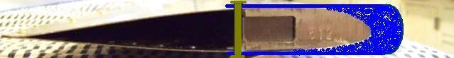
Can't move the bolt hole. C of G needs to move forward relative to the aero foil section. As the picture shows, there is plenty of room in the D-spar to drill a hole and place weight.
I'm thinking the best solution is to gun drill deep 3/8" or smaller holes in the D-spar root and tip, insert the proper weight of tungsten rod to bring the CWCG to 24.5% and use threaded plugs to hold the weights in. The root and tip weights could be adjusted in ratio to move their virtual mass spanwise to 70%.
Mike
Or in case you like to preserve most of structural integrity....
Few semi clamp weights in aerodynamic shape over whole span.
Epoxy - flox - lead shoot , epoxy glued and screwed tight.
At last spar can not crack first
Few semi clamp weights in aerodynamic shape over whole span.
Epoxy - flox - lead shoot , epoxy glued and screwed tight.
At last spar can not crack first
Join Date: Mar 2009
Location: Planet Earth
Age: 57
Posts: 75
Likes: 0
Received 0 Likes
on
0 Posts
Originally Posted by [email protected]
Chop off the trailing edge............
Brilliant one (lol)
But wouldn't that bring the CG further aft?
With chord balance what is the criteria ?
A blade that when suspended between centres on chord line lays at what angle, nose up, nose down, is there a optimum figure ?
A blade that when suspended between centres on chord line lays at what angle, nose up, nose down, is there a optimum figure ?