


North Sea heli ditching: Oct 2012

Thank you very much for the MGB illustration Wobblybob. Very enlightening.
So, the pump drive is on a short and very substantial shaft (with a high natural frequency presumably). The pumps are driven from independent gears. The general pattern is that ordinary gear sets are helical/spiral except for epicyclic sets AND the pump gears.
What are the relative positions of the two pumps around the central shaft?
Where is the shaft supported (including above the spiral bevel set)?
Is a range of different lubricants specified?
What is the normal range of lubricant operating temperature?
Are the pump gears changed at the same time as the shaft?
Is there only one type of pump on EC225?
Sorry. I'm really nosey when it comes to gears.
Last edited by jimf671; 19th Nov 2012 at 20:09.

What are the relative positions of the two pumps around the central shaft?
They are both on roughly the same side
Where is the shaft supported (including above the spiral bevel set)?
You can just about make out the machined bits where the bearings go, below and above the bevel
Is a range of different lubricants specified?
Yes, a modest range
What is the normal range of lubricant operating temperature?
Mid 80s C at max continuous power
Are the pump gears changed at the same time as the shaft?
Dunno! But shaft is lifed at 20,000 hrs I think
Is there only one type of pump on EC225?
yes, I think so ( if you mean MGB oil pump)
Sorry. I'm really nosey when it comes to gears.

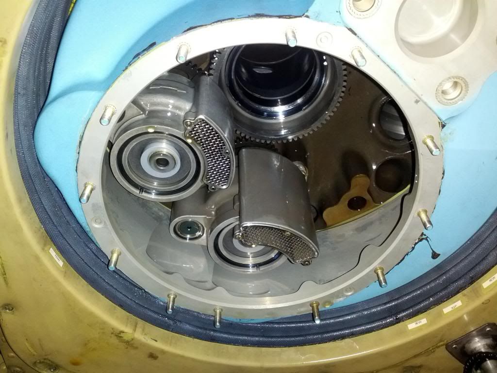
It's a long time ago but from what I remember the 330 Puma had the single oil pump on the back of the gearbox driven by No1 accessory drive. The shaft was hollow so that with a suitable bottom plate and drag damper oil reservoir a shaft could be extended above the rotor head for optical sighting equipment etc. Your photogragh also shows the No1 engine drive disconnect system where you could run No1 engine with the main rotor stationary but with operational No1 Alt and Hyd1 and drive it around on its own powered tracked undercarriage.
The early (up to the E model) did not have an oil pressure guage so the present problems would not happen. There was just a temperature guage and a MGP(P) on the SWP. A way of checking it was to pull up to about 80 degrees nose up; this would cause all the gearbox oil to flow to the rear of the gearbox, uncover the oil pump inlet followed by the pressure light.
In 1971 the Puma's max was 6,400 Kilos. I last flew them at 9,200.
Join Date: Feb 2009
Location: A nice place
Posts: 160
Likes: 0
Received 0 Likes
on
0 Posts
Just to clear up one point when the shaft breaks not only do you lose lubrication pumpsyou also loose the lower roller bearing that was supporting the shaft, now you are left with the ball and roller bearing on the other end. Bit like your hub cap coming of your car and taking a wheel bearing with it.
Pablo332.
Where did you get that theory from? If you look at the last photo you can see the structure above the oil pump gear ring (where the the cracking is) that supports the lower bearing of the rotor shaft.
Where did you get that theory from? If you look at the last photo you can see the structure above the oil pump gear ring (where the the cracking is) that supports the lower bearing of the rotor shaft.
Join Date: Mar 2012
Location: Somewhere
Posts: 3
Likes: 0
Received 0 Likes
on
0 Posts
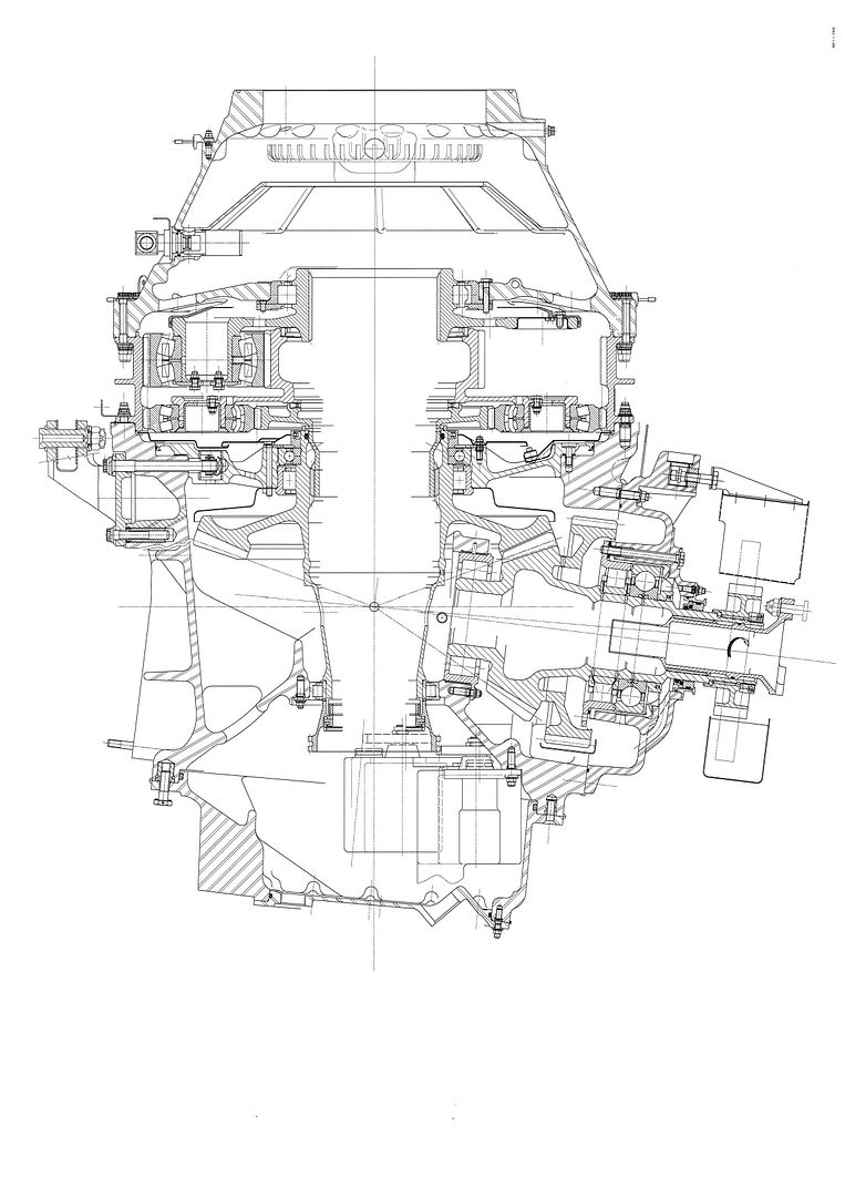
Just for others to clerify things please see drawing
there is actualy 3 sets of bearing, one set in the bottom of shaft, one just above where the shaft cracks, and one above the epicyclic gear
there is actualy 3 sets of bearing, one set in the bottom of shaft, one just above where the shaft cracks, and one above the epicyclic gear
Join Date: Feb 2009
Location: A nice place
Posts: 160
Likes: 0
Received 0 Likes
on
0 Posts
If you look at the last picture you will see a hole passing through the shaft wall the area where the shaft cracked is above that. The weld area is the next change in colour going up the shaft.
"If you look at the last picture you will see a hole passing through the shaft wall the area where the shaft cracked is above that. The weld area is the next change in colour going up the shaft."
The picture is very good, but not that good. Perspective and parallax play their parts and the best I can suggest is that you look up into an actual gearbox. Then it becomes clear that the weld and the adjacent fracture lines are below the bottom of the main rotor shaft bearing.
Here's another thought. Why would a design engineer allow a main rotor shaft to have any kind of weld between its top and bottom support bearings? That shaft in the picture is nowhere near robust enough to take much greater side loads than just the two oil pumps.
I even question why the oil pumps are next to each other, rather than on opposite sides of the driving gear, to mutually counteract sideways reactions to the torque forces driving them. (Excuse my lack of proper engineering terminology.)
Last edited by Colibri49; 20th Nov 2012 at 12:47.
Join Date: Feb 2009
Location: A nice place
Posts: 160
Likes: 0
Received 0 Likes
on
0 Posts
Looking at wobblybobs sectioned picture you have the oil pump drive gears on the bottom of the shaft, the shaft then tapers in a little to a parallel shiney section this is the location of the lower roller bearing. If you follow the shaft up it becomes obscured by the horizontal torque shaft. Just to the right of the torque indicating gubbins where the shaft reappears is a light coloured band on the main shaft running parallel to the torque shaft, this is where the crack occurred. Shaft length reduced by about half. 1/3 of the bearings now not doing anything.
Join Date: Feb 2009
Location: A nice place
Posts: 160
Likes: 0
Received 0 Likes
on
0 Posts
For anyone interested in the published facts on this incident http://www.stepchangeinsafety.net/about/GCHCNditchingincident.cfm is a goldmine of information. About halfway down the page the link to the EC ditching analysis provides some useful information, page 5 shows the location of the crack.
"Looking at wobblybobs sectioned picture you have the oil pump drive gears on the bottom of the shaft, the shaft then tapers in a little to a parallel shiney section this is the location of the lower roller bearing. If you follow the shaft up it becomes obscured by the horizontal torque shaft. Just to the right of the torque indicating gubbins where the shaft reappears is a light coloured band on the main shaft running parallel to the torque shaft, this is where the crack occurred. Shaft length reduced by about half. 1/3 of the bearings now not doing anything."
I understand why you think that the shiny parallel section is where a roller bearing sits, but it isn't so. Why it is shiny is beyond me. If you follow the sectioned picture further up the widening conical shaft, it is just possible to see the right-hand end of the welded join above the horizontal torque shaft.
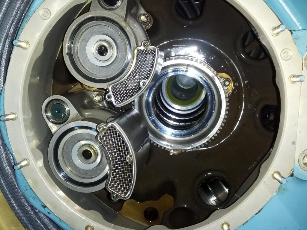
"Slightly better (?) angle of box"
Unfortunately not for this particular debate, but thanks.
I understand why you think that the shiny parallel section is where a roller bearing sits, but it isn't so. Why it is shiny is beyond me. If you follow the sectioned picture further up the widening conical shaft, it is just possible to see the right-hand end of the welded join above the horizontal torque shaft.
"Slightly better (?) angle of box"
Unfortunately not for this particular debate, but thanks.
Last edited by Colibri49; 20th Nov 2012 at 13:57.
It definitely cracked above the bottom bearing, leaving the 2 other bearings to support the main shaft, one being just above the bevel gear (and hence taking most of the bevel gear side loads). I thikn the intention is that the bottom bearing doesn't take much except the pump gear side loads