


R22 Delta-3, I don't think so

Thread Starter
Join Date: Jul 2001
Location: CT, USA
Posts: 68
Likes: 0
Received 0 Likes
on
0 Posts
R22 Delta-3, I don't think so
Delta-3 on a main rotor, such as the Robinson's, only pulls out a small percentage of the pitch that was input from the cyclic stick. I think that it is designed this way to make light helicopters easier to fly, just as the earlier Bells had counterweights and the Hiller had paddles. It may also help minimize the effect of gusts. Dave J.
____________________
____________________
This limits flapping. Since there is no cyclic control on a TR, phase lag in the controls is non-existent.
The R22 rotorhead is a so-called tri-hinge design, with Robinson calling the outboard hinges coning hinges. I don't think there is any reason to think that they are involved in flapping, since the blades in a teetering rotor flap as a unit about the central flapping hinge. Even a cyclic input merely rotates one blade up and one down and ,again, they move together as a unit. The blades flap alright, but always about the CENTRAL flap hinge.
Robinson maintains that the 18 degree phase offset was put in to compensate for certain cross coupling effects. The swashplate was rotated 18 degrees to accomplish this.
Think of it this way: if the coning hinges really did pull pitch out when you put in a cyclic input the resulting phase offset would need to be compensated for in the swashplate. That would mean additional swashplate offset would be needed to compensate for the other cross coupling effects such as right roll tendency with increasing airspeed.
I tend to think that Robinson merely rotated the swashplate and the blades do not in fact experience any delta-3 effect from flapping. They may flap independently of teetering, but if they do, it is a transient condition and would normally be suppressed due to the fact that any moment applied to the head will simply teeter the head to where the blades are once again in a straight line- well, straight except for the coning angle, which is what the hinges are there for.
I suppose that if the swashplate is rotated to a non 90 deg orientation that it's delta-3 by definition, "I just question whether on the R22, its also delta-3 by flap hinge geometry" as Dave J. calls it.
Last edited by Chiplight; 9th Mar 2007 at 04:56.

Join Date: Jan 2006
Location: Sydney, Australia
Age: 46
Posts: 25
Likes: 0
Received 0 Likes
on
0 Posts
Delta-3 does not have to be implemented by putting the flapping or teetering hinge at an angle. It can also be achieved through offsetting the pitch control horns relative to the axis of the flapping or teetering hinge.
Phase lag (rotation of the control cyclic control inputs from the 90 degree offset position) can occour through a number of causes. Delta-3 is one of them, flapping hinge offset is another. In the case of the r22, there is no flapping hinge offset (the two blades share a common flapping hinge - the teetering hinge), so the 18 degree phase lag is probably due to the delta 3 rigging.
Daniel
Thread Starter
Join Date: Jul 2001
Location: CT, USA
Posts: 68
Likes: 0
Received 0 Likes
on
0 Posts
Thanks. That is more or less what I was trying to say, but you said it better.
It would seem , then, that Frank R's description of pitch-flap coupling(posted here some time ago) is a bit misleading. He was explaning why the R22/R44 has 18 degrees of phase offset and said:
When the swashplate is not aligned with the rotor, the rotor will follow, but no pitch flap coupling occurs in the robby. The teetering rotor is unique in this respect. A gyroplane manages to have effective cyclic control without hinges of any kind other than the flap hinge. By tilting the head, both blades are "feathered" in unison.
It would seem , then, that Frank R's description of pitch-flap coupling(posted here some time ago) is a bit misleading. He was explaning why the R22/R44 has 18 degrees of phase offset and said:
Many helicopter engineers have difficulty understanding how delta-three (pitch-flap coupling) affects the phase relationship between the rotor disc and the swashplate. Delta-three only affects the phasing when the rotor disc is not parallel to the swashplate and there is one-per-rev aerodynamic feathering of the blades. For instance, feathering occurs while the rotor disc is being tilted, because an aerodynamic moment on the rotor disc is required to overcome the gyroscopic inertia of the rotor. But once the rotor disc stops tilting, the rotor disc and swashplate again become parallel and the delta-three has no effect on the phasing.
Last edited by Chiplight; 9th Mar 2007 at 15:48.
Join Date: Apr 2003
Location: Vancouver, BC, Canada
Posts: 1,635
Likes: 0
Received 0 Likes
on
0 Posts
Chiplight,
I still think so.
What you and Deemar say is correct, IMHO.
Perhaps the following will answer your concern.
The first two sketches on web page Pitch-Flap Coupling; (delta3, δ3), were stolen from 'Helicopter Theory' by Wayne Johnson. The sketch 'A/ By flap hinge geometry' shows an offset flapping hinge. However, the flapping hinges on both A/ and B/ can also be considered as teetering hinges. One must envision that the second blade was just not shown.
Dave
I still think so.
What you and Deemar say is correct, IMHO.
Perhaps the following will answer your concern.
"I just question whether on the R22, its also delta-3 by flap hinge geometry" as Dave J. calls it.
Dave
Join Date: Nov 2004
Location: Cambridgeshire, UK
Posts: 1,334
Likes: 0
Received 0 Likes
on
0 Posts
It's taken me a while to fully understand the D3 dynamics in an R22, but Frank Robinson's explanation (on Dave's site) does make sense. In a nutshell:
1. Rotor coning and inflow cross-coupling compensation.
2. Pitch and roll velocity cross-coupling compensation (wee-wa)
3. Vertical component gust reduction - more as a side effect.
4. Increase in revolutions to respond to cyclic input.
Point 4 could be seen as a problem, but since a teetering rotor has acceleration control for cyclic input until equilibrium establishes itself at a fixed pitch or roll rate, then this slow down in response probably makes the machine more flyable (once you learn not to overcontrol). The final proof is that it flies in the direction you point it.
Mart
Thread Starter
Join Date: Jul 2001
Location: CT, USA
Posts: 68
Likes: 0
Received 0 Likes
on
0 Posts
1. Rotor coning and inflow cross-coupling compensation.
2. Pitch and roll velocity cross-coupling compensation (wee-wa)
3. Vertical component gust reduction - more as a side effect.
4. Increase in revolutions to respond to cyclic input.
2. Pitch and roll velocity cross-coupling compensation (wee-wa)
3. Vertical component gust reduction - more as a side effect.
4. Increase in revolutions to respond to cyclic input.
This is done by rotating the swashplate. Delta-3 is not accomplished by flap hinge geometry in the R22 as I see it. The helicopter does fly where you point it. If it ALSO had pitch flap coupling, the 18 degree offset would need to be increased or decreased to match.
On point 3: A vertical gust will increase AOA and slightly increase coning.The pitch flap coupling, of course, will pull out pitch and limit the coning increase.
Rpm increases as coning goes up, but the drag of the rotor goes up with the AOA. The airframe may also pitch into the gust (a pitch stable response) reducing the effect. The rpm governor will limit excursions at any rate.
The whole effect may be small enough to ignore. Maybe I missed the point.
4. I don't see why there would be any tendency for rpm increase. Again going to the example of the tilt-head gyroplane- cyclic input consists of increasing the angle of one blade and decreasing the angle of the other as one unit and the rotor is forced to realign by precessing to a new plane. No flapping hinges needed, just a teeter hinge.
Dave, I'll now take a look at the drawings you mentioned and see if I understand what you are getting at.
Last edited by Chiplight; 10th Mar 2007 at 02:11.
Join Date: Nov 2004
Location: Cambridgeshire, UK
Posts: 1,334
Likes: 0
Received 0 Likes
on
0 Posts
Chiplight, i think you misunderstand point 4. All i am saying is that the 18 degrees D3 will reduce the cyclic input response time from 1/4 of a revolution to several revolutions. This just slows down cyclic response - Dave explains it well on his site. It may be one reason pilot has to learn to moderate his cyclic inputs (i was all over the place at first, with PIO in hover).
Point 3 is, as commented, is more a side effect of the D3 being there. As you correctly note, it will give a softer ride. So overall a benefit in being there.
I may not fully understand what you are saying here. All sorts of complicated machanical arrangements are possible. For a simple vertical pitch link D3 equals swashplate rotation from 90 degree lead. Pitch flap is accomplished, since as rotor teeters a pitch is also introduced. From
http://www.b-domke.de/AviationImages....html#Robinson
Mart
Point 3 is, as commented, is more a side effect of the D3 being there. As you correctly note, it will give a softer ride. So overall a benefit in being there.
Originally Posted by Chiplight
This is done by rotating the swashplate. Delta-3 is not accomplished by flap hinge geometry in the R22 as I see it. The helicopter does fly where you point it. If it ALSO had pitch flap coupling, the 18 degree offset would need to be increased or decreased to match.
http://www.b-domke.de/AviationImages....html#Robinson
Mart
Thread Starter
Join Date: Jul 2001
Location: CT, USA
Posts: 68
Likes: 0
Received 0 Likes
on
0 Posts
My mistake. 
I took a look at the image at
http://www.b-domke.de/AviationImages...t_020509l.html
and saw the pitch flap coupling, which I had forgotten was there. Somehow I got it in my head that the pitch links were coincident with the teeter axis and they're not.
Thanks Dave and Graviman for setting me straight. I hope this thread hasn't been too much a waste of "ink."
Join Date: Nov 2004
Location: Cambridgeshire, UK
Posts: 1,334
Likes: 0
Received 0 Likes
on
0 Posts
Originally Posted by Chiplight
Thanks Dave and Graviman for setting me straight. I hope this thread hasn't been too much a waste of "ink."
Mart
Join Date: Apr 2003
Location: Vancouver, BC, Canada
Posts: 1,635
Likes: 0
Received 0 Likes
on
0 Posts
Chiplight,
Thanks "for setting me straight".
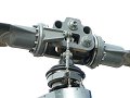
I have been under the impression that the pitch link was aligned with the axis of the coning hinge. Your linked picture appears to show that the pitch link is inboard of the coning hinge. If this is true, then upward coning will increase the pitch. All very interesting.
This tri-hinge rotor may also be of interest. Dynali helicopter
A 2-part question:
Is there any other helicopter that has a main rotor with delta3, and if so, what is its phase angle?
The Kaman helicopters have teetering rotors with delta3. However, their control is by servo-flap and this might have some unique effect on the phase angle.
Thanks.
Dave
Thanks "for setting me straight".
I have been under the impression that the pitch link was aligned with the axis of the coning hinge. Your linked picture appears to show that the pitch link is inboard of the coning hinge. If this is true, then upward coning will increase the pitch.
All very interesting.This tri-hinge rotor may also be of interest. Dynali helicopter
A 2-part question:
Is there any other helicopter that has a main rotor with delta3, and if so, what is its phase angle?
The Kaman helicopters have teetering rotors with delta3. However, their control is by servo-flap and this might have some unique effect on the phase angle.
Thanks.
Dave
Join Date: Nov 2004
Location: Cambridgeshire, UK
Posts: 1,334
Likes: 0
Received 0 Likes
on
0 Posts
Dave, pitch link doesn't need to be inside coning hinge for system to be stable. Don't forget that the coning will result from an increase in blade AOA to airflow in a gust. As long as pitch increase with coning is less than the gust AOA increase then system does not become divergent. Similarly if pilot pulls collective, then as long as coning pitch increase is less than that demanded the only effect is a more sensitive collective. The co-relator will sort out required engine power from the more sensitive collective. I imagine gust alleviation is more of an issue when the blade can directly transfer a pitch/roll moment.
BTW Dynali also has D3 since pitch links not normal to teetering plane.
I would imagine all helis have some D3, or if not rig the swash plate to correct for effects 1 and 2 above. The servo system might introduce a small response delay, but the rotor is nutating to the force ~90 degrees later, so probably makes no difference.
Mart
Join Date: Nov 2004
Location: Cambridgeshire, UK
Posts: 1,334
Likes: 0
Received 0 Likes
on
0 Posts
Dave, it could be a trick of perspective, but that photo on your site looks like rotor goes clockwise (from top). Pitch link also looks as if it has less lead than 90 degrees.
Mart
Mart
