


UK F-35B Lost

Join Date: Jul 2008
Location: Australia OZ
Age: 75
Posts: 2,575
Likes: 0
Received 51 Likes
on
45 Posts
In my research often USN NATOPS do not describe Carrier Approach Technique and may refer to a cryptic FCLP technique elsewhere. Recently I came across this short description below which may answer a few previous questions. I forgot about NIL Wind with the carrier having to make WOD issues.
NATOPS FLIGHT MANUAL 15 April 1968 Navy Model F-8A, F-8B AIRCRAFT
CARRIER-BASED PROCEDURES - CARRIER LANDING
"Refer to field carrier landing practice, this section, for additional information, to figure 3-11 for illustration of a typical carrier landing, and to section I, part 4 for carrier operating limitations. [Later I may excerpt the FCLP text]
While maneuvering to enter the traffic pattern, attempt to determine the sea state. [I believe these days the USN LSO gives this info or is given during marshal] This information will be of value in predicting problems that may be encountered during the ensuing approach and landing.
If the sea state is smooth, the carrier is creating all (or most) of the wind over the deck by hard steaming. Avoid entering the pattern at gross weights near the maximum since the approach speed could exceed the maximum engaging speed. Expect the wind to be down the axial deck which will result in a 10� crosswind when lined up with the angled deck. Stack wash will be encountered, so expect some turbulence when approaching the ship's wake. Pay particular attention to lineup.
With a moderate sea state, the carrier should be able to place the wind down the angled deck so lineup will not be a problem. As the wind over deck increases, additional power will be required to fly a proper approach.
If blowing spray is observed the sea state is rough and the carrier will be steaming to maintain steerageway. The wind over deck will be gusty which will necessitate more frequent power and control corrections to maintain the glide slope. Turn earlier at the 180� position to avoid being long in the groove.
PATTERN
Enter with a level break from a course parallel to Foxtrot Corpen, close aboard the starboard side of the ship at 800 feet MSL. If in formation, maintain a break interval of 12 to 16 seconds. When on downwind leg, descend to 600 feet and perform cockpit check. Engage and check operation of the approach power compensator. Cross-check angle-of-attack and airspeed indicator. Check cockpit emergency ventilation port closed before using angle-of-attack indications. Fly a racetrack pattern with the 180� position approximately 1� miles abeam (check distance with TACAN, if desired) at 600 feet MSL. With a 30-knot wind over deck, begin the 180� turn to the final approach when approximately abeam the LSO platform. To be lined up with the angled deck centerline, roll out immediately to the right of the ship's wake. When the meatball is acquired, transmit call sign, fuel state (nearest 100 pounds), "Crusader" and "meatball." Signify no meatball by transmitting the code word "Clara."
GLIDE SLOPE
The physical glide slope projected from the ship is approximately 4�. Due to the wind over the deck, the aircraft flies approximately a 3.25� slope through the air. However, at any given point in the approach, the pilot is looking at the ship on a 4� slope. This, of course, gives the pilot the feeling that he is too high. This feeling should be disregarded, and only the meatball should be relied upon for proper glide slope control. Closure rate on the ship is on the order of 105 knots, whereas on the field, closure rate is usually equal to true airspeed (light wind). This difference in "distance/time" relationship further emphasizes the need for looking at, and flying the meatball all the way to touchdown, rather than estimating power required by looking at the deck. It is necessary to carry a little more power on the glide slope on the ship than ashore, in order to maintain the proper glide slope and airspeed.
FLYING THE MEATBALL
Use of the approach power compensator is recommended for all carrier landings. An occasional manual approach will suffice to maintain proficiency. The approach power compensator should not be used if operating in manual fuel control or if the wing cannot be raised.
Initial Approach
After rolling wings level on the final approach, begin a rate of descent of approximately 600 feet per minute. Average out the meatball movement. Maintain a glide path that shows the same degree, or distance, of meatball movement above and below the datum lights.
Middle Approach
As the aircraft progresses into the middle third of the approach, meatball movement due to carrier pitch is at a minimum. Use this part of the approach to advantage. Adjust nose attitude and establish the proper rate of descent.
Final Approach
As the aircraft moves into the final third of the approach, the meatball will again begin to cycle on the optical landing system. Hold the power setting and the rate of descent established during the middle third of the approach, unless instructed otherwise by the LSO. If the meatball goes high when approaching the ramp, do not attempt to center it. The ramp could be cycling down, and an increased rate of descent, coupled with a rising ramp on touchdown, could exceed aircraft design limits. If the meatball starts to go low, do not hesitate to override the approach power compensator by adding power. In this case, the aircraft could be descending below the glide path, or the ramp could be cycling up. In either event, the aircraft is getting too dose to the ramp and the only correction is power. Accept the fact that wave-off and bolter rates increase when landing with a pitching deck. The higher rates are acceptable, particularly when the alternatives are considered (hard landings, ramp contacts, etc).
FOULED-DECK WAVE-OFF
Don't anticipate a fouled-deck wave-off. Aircraft will repeatedly clear the landing area fractions of a second before the wave-off point is reached, and a clearance to land will be received. Let the LSO give the wave-off. Wave-off characteristics are good and the engine accelerates from approach thrust (about 84% rpm) to military thrust in about 2.5 seconds.
CLOSE-IN WAVE-OFF
Avoid a close-in wave-off whenever possible. However, if it becomes necessary, move the throttle smartly to MRT or CRT and maintain optimum landing attitude. Do not overrotate. Maintain a wings level flight attitude.
NATOPS FLIGHT MANUAL 15 April 1968 Navy Model F-8A, F-8B AIRCRAFT
CARRIER-BASED PROCEDURES - CARRIER LANDING
"Refer to field carrier landing practice, this section, for additional information, to figure 3-11 for illustration of a typical carrier landing, and to section I, part 4 for carrier operating limitations. [Later I may excerpt the FCLP text]
While maneuvering to enter the traffic pattern, attempt to determine the sea state. [I believe these days the USN LSO gives this info or is given during marshal] This information will be of value in predicting problems that may be encountered during the ensuing approach and landing.
If the sea state is smooth, the carrier is creating all (or most) of the wind over the deck by hard steaming. Avoid entering the pattern at gross weights near the maximum since the approach speed could exceed the maximum engaging speed. Expect the wind to be down the axial deck which will result in a 10� crosswind when lined up with the angled deck. Stack wash will be encountered, so expect some turbulence when approaching the ship's wake. Pay particular attention to lineup.
With a moderate sea state, the carrier should be able to place the wind down the angled deck so lineup will not be a problem. As the wind over deck increases, additional power will be required to fly a proper approach.
If blowing spray is observed the sea state is rough and the carrier will be steaming to maintain steerageway. The wind over deck will be gusty which will necessitate more frequent power and control corrections to maintain the glide slope. Turn earlier at the 180� position to avoid being long in the groove.
PATTERN
Enter with a level break from a course parallel to Foxtrot Corpen, close aboard the starboard side of the ship at 800 feet MSL. If in formation, maintain a break interval of 12 to 16 seconds. When on downwind leg, descend to 600 feet and perform cockpit check. Engage and check operation of the approach power compensator. Cross-check angle-of-attack and airspeed indicator. Check cockpit emergency ventilation port closed before using angle-of-attack indications. Fly a racetrack pattern with the 180� position approximately 1� miles abeam (check distance with TACAN, if desired) at 600 feet MSL. With a 30-knot wind over deck, begin the 180� turn to the final approach when approximately abeam the LSO platform. To be lined up with the angled deck centerline, roll out immediately to the right of the ship's wake. When the meatball is acquired, transmit call sign, fuel state (nearest 100 pounds), "Crusader" and "meatball." Signify no meatball by transmitting the code word "Clara."
GLIDE SLOPE
The physical glide slope projected from the ship is approximately 4�. Due to the wind over the deck, the aircraft flies approximately a 3.25� slope through the air. However, at any given point in the approach, the pilot is looking at the ship on a 4� slope. This, of course, gives the pilot the feeling that he is too high. This feeling should be disregarded, and only the meatball should be relied upon for proper glide slope control. Closure rate on the ship is on the order of 105 knots, whereas on the field, closure rate is usually equal to true airspeed (light wind). This difference in "distance/time" relationship further emphasizes the need for looking at, and flying the meatball all the way to touchdown, rather than estimating power required by looking at the deck. It is necessary to carry a little more power on the glide slope on the ship than ashore, in order to maintain the proper glide slope and airspeed.
FLYING THE MEATBALL
Use of the approach power compensator is recommended for all carrier landings. An occasional manual approach will suffice to maintain proficiency. The approach power compensator should not be used if operating in manual fuel control or if the wing cannot be raised.
CAUTION
It may become desirable to make a manual approach, instead of an APC approach,
under unfavorable approach conditions such as gusty or extremely high winds.
The technique for flying the meatball during steady deck operation approximates that used during FMLP [Field Mirror Landing Practice or MADDLS in the old lingo Mirror Assisted Dummy Deck Landings]. However, with increasing rough seas the glide slope varies, particularly in the vertical plane. With a point-stabilized Fresnel lens, the glide slope is stabilized only to the extent that it passes through a point in space 1,800 to 2,200 feet astern (approximately half way out on the final approach). As the deck pitches, the glide slope deflects as necessary to remain focused on this point. It is apparent that the vertical movement of the glide slope increases in magnitude as distance from the focal point increases. With a line stabilized lens, the glide slope is stabilized for all ship movement except heave. No meatball movement due to deck motion should be discernible to the pilot, except under the most severe conditions.It may become desirable to make a manual approach, instead of an APC approach,
under unfavorable approach conditions such as gusty or extremely high winds.
Initial Approach
After rolling wings level on the final approach, begin a rate of descent of approximately 600 feet per minute. Average out the meatball movement. Maintain a glide path that shows the same degree, or distance, of meatball movement above and below the datum lights.
Middle Approach
As the aircraft progresses into the middle third of the approach, meatball movement due to carrier pitch is at a minimum. Use this part of the approach to advantage. Adjust nose attitude and establish the proper rate of descent.
Final Approach
As the aircraft moves into the final third of the approach, the meatball will again begin to cycle on the optical landing system. Hold the power setting and the rate of descent established during the middle third of the approach, unless instructed otherwise by the LSO. If the meatball goes high when approaching the ramp, do not attempt to center it. The ramp could be cycling down, and an increased rate of descent, coupled with a rising ramp on touchdown, could exceed aircraft design limits. If the meatball starts to go low, do not hesitate to override the approach power compensator by adding power. In this case, the aircraft could be descending below the glide path, or the ramp could be cycling up. In either event, the aircraft is getting too dose to the ramp and the only correction is power. Accept the fact that wave-off and bolter rates increase when landing with a pitching deck. The higher rates are acceptable, particularly when the alternatives are considered (hard landings, ramp contacts, etc).
FOULED-DECK WAVE-OFF
Don't anticipate a fouled-deck wave-off. Aircraft will repeatedly clear the landing area fractions of a second before the wave-off point is reached, and a clearance to land will be received. Let the LSO give the wave-off. Wave-off characteristics are good and the engine accelerates from approach thrust (about 84% rpm) to military thrust in about 2.5 seconds.
CLOSE-IN WAVE-OFF
Avoid a close-in wave-off whenever possible. However, if it becomes necessary, move the throttle smartly to MRT or CRT and maintain optimum landing attitude. Do not overrotate. Maintain a wings level flight attitude.
WARNING
Accept a touchdown short of the number one cross-deck pendant, accept a bolter,
but do not overrotate and do not turn. In the event of a ramp strike, select afterburner...."
https://www.docdroid.com/3rcAqOj/vou...ght-manual-pdf (40Mb)Accept a touchdown short of the number one cross-deck pendant, accept a bolter,
but do not overrotate and do not turn. In the event of a ramp strike, select afterburner...."
Last edited by SpazSinbad; 28th Dec 2021 at 08:28. Reason: format + grfx

Join Date: Feb 2006
Location: Hanging off the end of a thread
Posts: 32,855
Received 2,809 Likes
on
1,196 Posts
Join Date: Jul 2008
Location: Australia OZ
Age: 75
Posts: 2,575
Likes: 0
Received 51 Likes
on
45 Posts
Only the A-4E/F had APC (when modified). The A4G in RAN FAA service did not have APC. I looked in the F-8 NATOPS & online info for APC knowledge but nowt, so the description from the Skyhawk NATOPS will have to do for now.
A-4E/F & A4G Skyhawk NATOPS 1968
"Approach Power Compensator
The approach power compensator (APC) system is installed in aircraft reworked per A-4 AFC 268-1-11-III. The APC controls the fuel control and is designed to maintain the optimum angle of attack of 17.5 units resulting in an optimum approach speed on the glide slope and during normal maneuvers in the landing pattern at any landing gross weight. Major APC components are the computer, amplifier, servo actuator, accelerometer, elevator potentiometer, angle-of-attack vane transducer, and the APC control panel.
The APC is designed to command throttle position between an approximate 70 percent rpm and an approximate military rated thrust (MTR) in response to angle of attack. The angle-of-attack signal is modified by normal acceleration and elevator control stick position. If the APC is engaged or operating when aircraft angles of attack are greater than or less than optimum, the APC will compensate by increasing or decreasing throttle position accordingly. At angles of attack greater than optimum, the APC will command an increasing throttle position until MRT (approximate) is attained or the angle of attack returns to optimum. Conversely, at angles of attack less than optimum, the APC will command a decreasing throttle position until 70 percent (approximate) rpm is attained or the angle of attack returns to optimum." [URL below is for a direct FREE - no subscription required - download to PDF described]
OneDrive: _A4G_NATOPS_Text_Searchable+BookMarks.PDF (139Mb)
https://1drv.ms/b/s!AuYHBzTWY83LikE-...4XQ5k?e=NWQNM8
Last edited by SpazSinbad; 28th Dec 2021 at 15:28. Reason: format
Join Date: Jul 2008
Location: Australia OZ
Age: 75
Posts: 2,575
Likes: 0
Received 51 Likes
on
45 Posts

F-35 Subsystems Design, Development & Verification 2018
"Ejection System The auto-escape system is configured in the F-35B only for the event of catastrophic failure of the LiftFan�. Such a failure can produce a rapid onset of forward pitch accelerations, perhaps exceeding the pilot’s ability to react and manually eject. The system is designed to provide detection of inertial attitudes and rates in the pitch-down plane within tolerances to filter out normal flight control input and response. The detection occurs in the control law software application of each VMC [vehicle management computer] during conditions in which the system is armed."
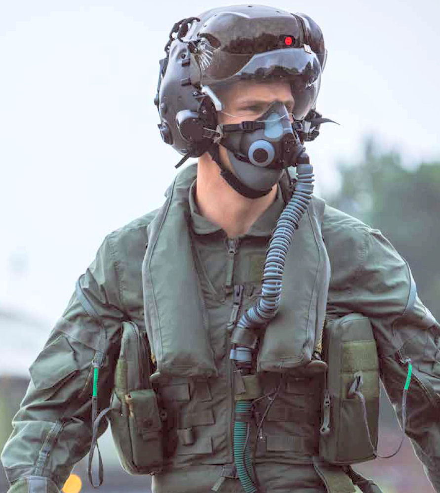
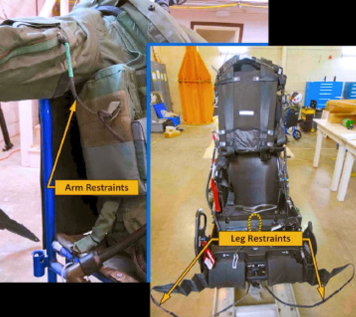
"US16E arm & leg restraints A second feature of the US16E ejection seat is the active arm and leg restraint. To minimize injury due to arm and leg flail during ejection, the US16E actively restrains the pilot’s arms and legs during ejection. It uses fabric lines that are integrated into the pilot’s flight ensemble. During ejection, the legs are drawn back and the arms are drawn to the lap and held until the lines have been severed. Figure shows the US16E arm and leg restraint system."
Last edited by SpazSinbad; 8th Jan 2022 at 06:40. Reason: + txt & JPeg
Join Date: Jul 2008
Location: Australia OZ
Age: 75
Posts: 2,575
Likes: 0
Received 51 Likes
on
45 Posts
Not being an ex-STOVL pilot I was intrigued to find more about STOs in light of the question about catapulting and wind direction earlier. Other PDFs have described from the test pilot viewpoint what is it like to STO from an LHA however this 15 page PDF addresses the 'WIND' question & other STO questions.
F-35 STOVL Performance Requirements Verification by LM & others staff 2018
"...An element of ship [USN LHA] operations that could not be evaluated during shore-based testing was the variation of ambient wind over the [flat] deck of the ship. The amount of headwind and crosswind the aircraft experiences during a STO is a function of the magnitude and direction of the ambient wind and the speed, pitch, and roll of the ship. It is also affected by the position of the aircraft along the STO launch tram line and its location relative to the ship’s superstructure. The environment can be very unsteady and unpredictable...."
Last edited by SpazSinbad; 10th Jan 2022 at 00:30. Reason: spulin
Join Date: Jul 2008
Location: Australia OZ
Age: 75
Posts: 2,575
Likes: 0
Received 51 Likes
on
45 Posts
Computational and experimental modelling study of the unsteady airflow over the aircraft carrier HMS Queen Elizabeth
Ocean Engineering Volume 172, 15 January 2019, Pages 562-574
https://www.sciencedirect.com/scienc...29801818318705 (PDF 6Mb)
"...Fig. 25 shows computed mean streamlines over the bow of the ship in a headwind, demonstrating the smooth air flow and the effectiveness of the bow design....
...5.1. Air flow over the full-scale flight deck
Fig. 27 shows the mean air flow over the QEC in a headwind, illustrated by mean streamlines in vertical planes that are aligned with the oncoming wind and pass through the landing spots (spots 1 to 5 along the length of the deck and spot 6 behind the aft island). The streamlines are coloured by turbulence intensity....
...While it is preferable to launch and recover aircraft to the ship in a headwind, where there will be less flow disturbance over the flight deck and higher relative air speeds, and hence lift for the aircraft, there will inevitably be times when the relative wind will be from directions other than ahead. It is important, therefore, to have an understanding of the air flow over the deck for all wind directions...."
Join Date: Jul 2008
Location: Australia OZ
Age: 75
Posts: 2,575
Likes: 0
Received 51 Likes
on
45 Posts
An excellent 25 minute fillum - although dated - explanation of USN Carrier Ops with the A-7 Corsair [reference to crabbing approach?]
"A-7 CORSAIR II FAMILIARIZATION" U.S. NAVY AIRCRAFT CARRIER FLIGHT DECK LANDING PROCEDURES 80184
"A-7 CORSAIR II FAMILIARIZATION" U.S. NAVY AIRCRAFT CARRIER FLIGHT DECK LANDING PROCEDURES 80184
Last edited by Senior Pilot; 22nd Jan 2022 at 00:18. Reason: Add image
Join Date: Jul 2008
Location: Australia OZ
Age: 75
Posts: 2,575
Likes: 0
Received 51 Likes
on
45 Posts
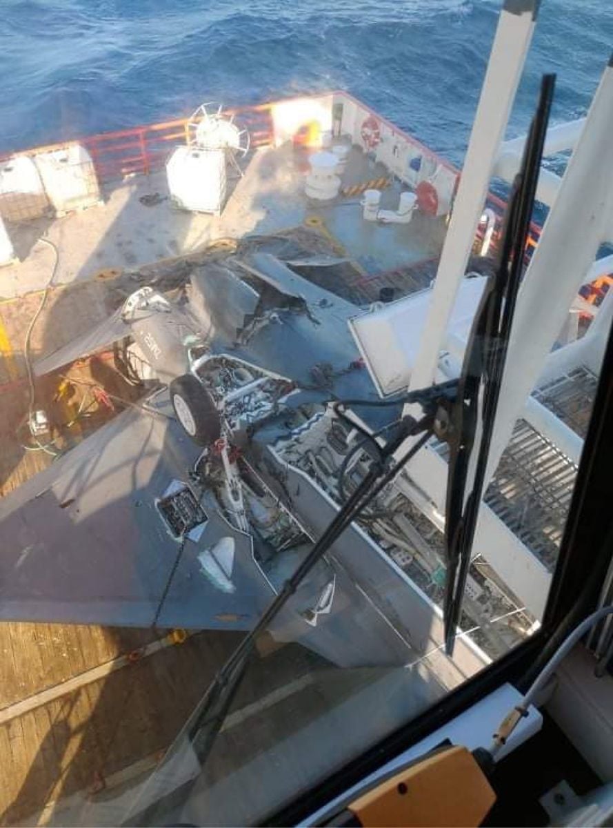
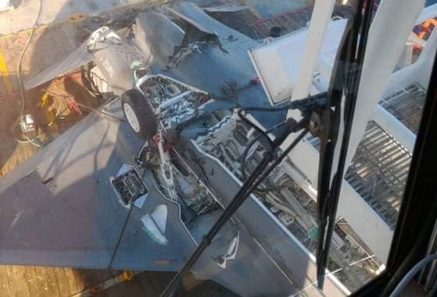
Why not. I'm not familiar with serial numbers of UK F-35Bs as seen in this ZOOM.

Last edited by SpazSinbad; 20th Jan 2022 at 10:19. Reason: + crop circle JPG
Without belaboring the obvious, the airplane is upside-down. Since it probably didn't get flipped on the recovery, and given the likely scenario and the dynamics involved, one suspects that it flipped beyond the vertical before it hit the water. In which case the pilot may well owe his life to auto-eject.
Without belaboring the obvious, the airplane is upside-down. Since it probably didn't get flipped on the recovery, and given the likely scenario and the dynamics involved, one suspects that it flipped beyond the vertical before it hit the water. In which case the pilot may well owe his life to auto-eject.

It seems incredibly unlikely that a largely-intact aircraft is going to sink through a vertical mile of water and then come to a rest on the bottom in the same orientation it hit the water. Think what happens if you leave a poorly-trimmed aircraft to its own devices in the air.
I believe it is enabled in STOVL mode, including STO, because the same issue can apply - a burp in the powered-lift system can cause a rapid departure to an out-of-envelope attitude. LAL may have information as to this specific case.