Ok, second picture (can anyone tell me how to attach more than one?)
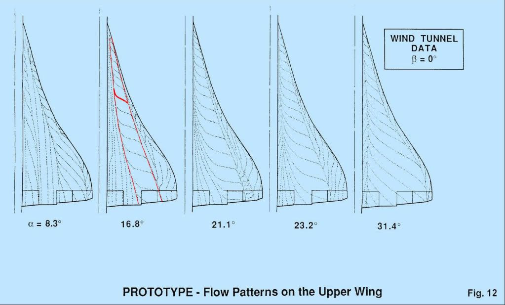
These need a bit of explaining I'm afraid. They are 'oil flow' pictures - you paint the model wing with a mixture of paraffin, engine oil and lamp black and blow air over it. The resulting pattern shows how the air is flowing (or not flowing, which is its primary purpose) over the wing surface.
I the diagram marked up in red the 'S' shaped line is a typical streamline where the air is brought down onto the surface inboard, moves downstream and across towards the tip under the combined action of fore and aft velocity and vortex rotational velocity and tis finally lifted off the surface by the vortex. the triangular zone marked out in red is the area of the wing 'scrubbed' by the vortex flow. If you compare the pictures at various AoA you will see that this area increases substantially as AoA increases.
On the21 deg picture you can also see signs of a second vortex between the main vortex and the wingtip, but this is not the classic 'tip vortex'
CliveL