


Qantas A380 uncontained #2 engine failure

Guest
Posts: n/a
In fact, if one looks closely at the diagram, the join of the fore/aft Shafts, with its splines, is likely the source of the Oil combustion evidence in the bearing case for Second and Third Ball bearings. Here, in the Slip area, with splines worn, a rogue gas path would deposit Carbon rich deposits on the LPT Shaft (see pic). Such a "leak" would also explain loss of (some) N2.
Join Date: Feb 2008
Location: U.K.
Posts: 62
Likes: 0
Received 0 Likes
on
0 Posts
The way I look at it is that although a shaft consists of two half shafts, the half shafts are joined at a rigid coupling so that they behave exactly as if they were a single unit. We do not know the secrets of the coupling itself except that it consists in part of a splined joint transmitting torque from the turbine to the compressor and at least one other element transmitting axial loads between the half shafts (because the splined joint alone cannot transmit axial tension).
The fact that wear rates in the coupling of some engines were found to be higher than expected does not mean that the coupling was anywhere near close to failing. I would assume that at some stage the wear develops to the point where movement in the joint goes out of acceptable limits and has to be removed but this would be well before a hazardous situation is reached.
The fact that wear rates in the coupling of some engines were found to be higher than expected does not mean that the coupling was anywhere near close to failing. I would assume that at some stage the wear develops to the point where movement in the joint goes out of acceptable limits and has to be removed but this would be well before a hazardous situation is reached.
Last edited by firstfloor; 23rd Dec 2010 at 14:28.

Guest
Posts: n/a
firstfloor (with apologies to wingsfolded)
You have essentially encapsulated the AD itself. There is concern that spline wear can lead to aft migration of the Aft Shaft, so indeed the Splines DO attenuate Axial movement, through the abutment face referenced in the AD. If one reads the Current AD, and prior AD's incorporated by Reference to them, one knows that the wear limit for the Spline is approximately 2mm, as measured on the "crest" of the Spline.
The Splines are helical, and allow for some inter rotation as the Thrust goes from Drive to Driven. Notice that the only (ball) bearing supporting the Aft IP Shaft is the #2 Thrust (Ball) bearing, and that this Shaft is directly supported through the Spline interface.
Nothing has been released as to exactly where the "Oil Fire" took place. Some assume at the Roller Bearings just forward of the IP Disc, others (myself) believe the fire occurred in the cavity containing IPC and HPC ball bearings. The telltale on the LPT Shaft suggests placement directly inside the joint where the Fore and Aft IP Shafts connect. The Aft IP Shaft end does not extend through the width of the Thrust bearing, meaning that all the energy between the two Shafts, is borne through a narrow section of the Splined Joint.
Keep in mind also that the Splines DO attenuate thrust (resist it), though not completely, they terminate at a ring that effaces the inner race of #2 Ball Bearing. Also take note that only a short section of Splines needs to fail to allow aft travel, they do not need to fail utterly.
I can appreciate your concern, but this is not nonsense.
Last edited by bearfoil; 24th Dec 2010 at 14:20.
Join Date: Feb 2008
Location: U.K.
Posts: 62
Likes: 0
Received 0 Likes
on
0 Posts
There is concern that spline wear can lead to aft migration of the Aft Shaft, so indeed the Splines DO attenuate Axial movement
The QF32 related AD's are not linked to the spline wear AD.
Guest
Posts: n/a
Please look at the Picture of the Aft LP Shaft. Take note of the soot ring. Locate that evidence under the Spline joint. Notice the well defined after portion of this ring of soot. From this well defined border, note that the soot seems to lighten and form a less sharp terminus as it moves forward.
High pressure oil fire gases have exited the Spline Joint at the connection of the two IP Shafts. Entering the space between the IP Shaft and LP Shaft, they encounter P30 pressure and quickly are routed forward. They continue to move forward and out the LP cowling, showing the Sooty streaks on the cowl.
The original AD has not been satisfied Publicly. RR is doing work that is under a device, an umbrella if you will, addressing a Duff Tube, as if it caused everything. No reporting of this "work" is ongoing. This engine has deeply problematic issues that degrade internals such that an inspection cycle of every third landing was proposed and enforced.
These issues? Every impact that can be imagined on Splines that historically have a virtual 100 per cent record. Metal in the Oil? Residue? Failed Oiling Couples? How much of Rolls Royce's authority as to compliance and airworthiness is to be respected (Other than by EASA) when they don't disclose serious issues to their clients? Rolls is doing workarounds under the cover of one tube that may not have been onboard. It is outrageous that EASA leaves to the Manufacturer all authority for airworthiness.
FAA FOIA
Join Date: Feb 2008
Location: U.K.
Posts: 62
Likes: 0
Received 0 Likes
on
0 Posts
That�s hardy a forensic analysis Bearfoil. Since they are based on very nearly zero evidence, your conclusions have to be taken as extremely dubious if not completely mad (I regret to say).
Join Date: Dec 2010
Location: Middle America
Age: 84
Posts: 1,167
Likes: 0
Received 0 Likes
on
0 Posts
firstfloor & bearfoil,
To see the shaft couplings in perhaps more detail, go to this site and click on the Trent 500 icon. Granted it is a Trent 500 and not a Trent 900, but I bet not much has changed relative to the general layout/architecture.
Portfolio of Technical Illustrations, Aviation Cutaway Drawings (Ghosted Drawings) & Technical Art. Info Graphics from Flightline Arts, UK.
Hope this is helpful.
Join Date: Feb 2008
Location: U.K.
Posts: 62
Likes: 0
Received 0 Likes
on
0 Posts
Yes, that's nice stuff. Thankyou. Simplest illustration to follow is front end of the Honeywell AS907 showing nut and spline. Axial load through the nut, torsion in the spline. Very common and simple type of joint - never goes wrong, apparently.
Simplest illustration to follow is front end of the Honeywell AS907 showing nut and spline. Axial load through the nut, torsion in the spline. Very common and simple type of joint - never goes wrong, apparently.


Join Date: Dec 2010
Location: France
Posts: 10
Likes: 0
Received 0 Likes
on
0 Posts
TheTrent 500 cutaway is very good, one can clearly see the bearing box and the scavange oil pipe going downward from the box. Here how such a box works in principle:
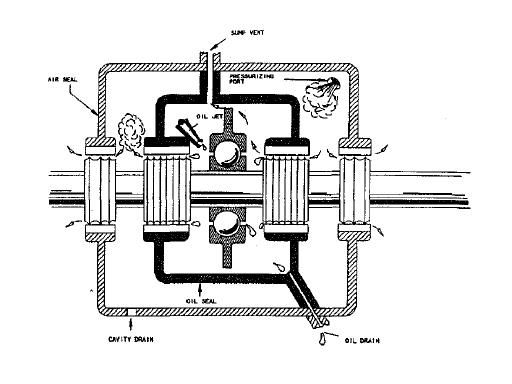
Bleed air is used to keep the outer box under pressure, the labyrinth seals has air pushing any oil back into the inner bearing box.
Bleed air is used to keep the outer box under pressure, the labyrinth seals has air pushing any oil back into the inner bearing box.
Join Date: Dec 2010
Location: S 51 N
Age: 84
Posts: 196
Likes: 0
Received 0 Likes
on
0 Posts
Trent 900 cutaway
here is a similar cutaway
http://www.rolls-royce.com/Images/br...cm92-11346.pdf
I like that, shows all the technical delicacy of that desighn.
Jo
http://www.rolls-royce.com/Images/br...cm92-11346.pdf
I like that, shows all the technical delicacy of that desighn.
Jo
Join Date: Jul 2007
Location: Virginia, USA
Age: 86
Posts: 77
Likes: 0
Received 0 Likes
on
0 Posts
Turbine D:
Most helpful. Every pixel of added resolution gets up closer to understanding what is going on.
Are those widgets in the center of the pix on the large piping what we used to see as clamps on automobile radiator hoses?
OE
To see the shaft couplings in perhaps more detail, go to this site and click on the Trent 500 icon. Granted it is a Trent 500 and not a Trent 900, but I bet not much has changed relative to the general layout/architecture.
Portfolio of Technical Illustrations, Aviation Cutaway Drawings (Ghosted Drawings) & Technical Art. Info Graphics from Flightline Arts, UK.
Hope this is helpful.
Portfolio of Technical Illustrations, Aviation Cutaway Drawings (Ghosted Drawings) & Technical Art. Info Graphics from Flightline Arts, UK.
Hope this is helpful.
Are those widgets in the center of the pix on the large piping what we used to see as clamps on automobile radiator hoses?
OE
Last edited by Old Engineer; 23rd Dec 2010 at 22:48. Reason: Added quote as reply was away from Turbine D's post
Join Date: Jul 2007
Location: Virginia, USA
Age: 86
Posts: 77
Likes: 0
Received 0 Likes
on
0 Posts
lomapaseo wrote, quoting firstfloor:
lomapaseo, I have to apologize for thinking that you could not see the problem that splines could present. And a sense of humor as well
If I may impose on that sense of humor to partially quote you from back at #1816 back at page 91, on 12th December:
I assume that the pix you posted was not damage due to a can opener being left in the turbine .
OE
Quote:
Simplest illustration to follow is front end of the Honeywell AS907 showing nut and spline. Axial load through the nut, torsion in the spline. Very common and simple type of joint - never goes wrong, apparently.
Well allmost never
Simplest illustration to follow is front end of the Honeywell AS907 showing nut and spline. Axial load through the nut, torsion in the spline. Very common and simple type of joint - never goes wrong, apparently.
Well allmost never
If I may impose on that sense of humor to partially quote you from back at #1816 back at page 91, on 12th December:
I don,t understand the hypothesis relative to this A380 thread of a link between thrust or tenperature to the failure causes 
That's as much of a stretch as most of the other technical sounding discussions in this Rumors & News forum.
That's as much of a stretch as most of the other technical sounding discussions in this Rumors & News forum.
.OE
Join Date: Dec 2010
Location: Middle America
Age: 84
Posts: 1,167
Likes: 0
Received 0 Likes
on
0 Posts
Old Engineer
They sure look some on automobiles I have owned
Turbine D
Are those widgets in the center of the pix on the large piping what we used to see as clamps on automobile radiator hoses?
Turbine D
Join Date: Feb 2005
Location: flyover country USA
Age: 82
Posts: 4,579
Likes: 0
Received 0 Likes
on
0 Posts
Ferpe - That sump ("bearing box") sketch looks a lot like one I recall seeing in some GE CF6 orientation literature, but I'm sure the Trent is similar in concept. One complication might be bearings on concentric shafts, though.
Join Date: Dec 2010
Location: France
Posts: 10
Likes: 0
Received 0 Likes
on
0 Posts
Yes, the between HP and IP shafts there is a space where the oil can go outwards (red 1 in picture) and follow the IP shaft forwards, there seems to be a labyrinth between the IP and HP shafts at the line from 2 in the picture.
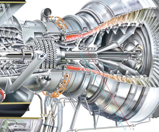
I guess they use the same principle here, a labyrinth sealing with a higher pressure in the space between the HP and IP shaft then the inner bearing area.
I guess they use the same principle here, a labyrinth sealing with a higher pressure in the space between the HP and IP shaft then the inner bearing area.
Join Date: Dec 2010
Location: Middle America
Age: 84
Posts: 1,167
Likes: 0
Received 0 Likes
on
0 Posts
Annex14
Thanks for the Trent 900 cutaway. Although it is only a sketch as the Trent 500 cutaway was, it gives some indications of changes that were made, particularly in the area of the IPT rotor and Stage 1 LPT nozzle that has been puzzling me.
First, I am pretty convinced that the fire caused by oil leakage (broken feed line) occurred in this area and was the instigator of the subsequent events leading to catastrophic failure of the components in this area of the engine.
In the Trent 500 engine series, there have been two failures in this same area. One failure has been identified as to coking instigating a fire causing the IPT rotor to fail at the disc rear drive arm 580 bolt holes. The second failure (Qantas B-747 out of SFO) is still under investigation by the ASTB, no cause yet given. However, in both cases the failures were uncontained. In both cases the IPT rotor moved rearward wiping out the Stage 1 LPT nozzle ring and the casing holding the nozzle ring as well as eliminating all the IPT rotor blades. In both cases, the IPT disc did not rupture but there was considerable damage to the LPT nozzles and blades as quite a bit of the debris went through the turbine. So why did the IPT rotor disc not rupture on these engines, but did on the Qantas A-380? All three aircraft were in a climb out mode, with the A-380 at an initial stage, the other two at 20,000+ feet altitude. In making the assumption that all three experienced a fire at or around the IPT rotor, the answer may be some changes made in the Trent 900 engine verses what is present in the Trent 500 engine. In particular, note the gap between the IPT rotor blades and the leading edge of the airfoils of Stage 1 LPT nozzle on the Trent 900. Compare it to the gap present on the Trent 500.
In the design of rotor/stator interfaces in this area of the engine, two important considerations must be addressed, fire and shaft breakage. If the rotor is released due to one or the other, the design should assure that the airfoils come in contact first as a breaking mechanism to prevent disc overspeed and subsequent possibility of a disc burst. The reason for this is a term called "False Bearings". If the disc or a portion thereof contacts first, there is sufficient energy present to melt the contact surfaces and momentarily make a low friction bearing long enough to allow overspeed to occur. This liquid metal bearing is referred to as the "false bearing". Often, the LPT nozzle airfoils have their leading edges bowed outward to assure first contact with the IPT rotor blades should a disconnect occur.
Because of the closeness of these airfoils in the Trent 500, blade to nozzle contact prevented IPT disc overspeed. But in the Trent 900, note the Stage 1 LPT nozzle airfoils are more rearward precluding contact and breaking effect before overspeed occurs.
So my thought is the oil fire and temperatures in the cavities "softened the IPT rotor disc, causing the rear drive arm to fail, the rotor moved aft, but the blades didn't contact the nozzle airfoils first causing a disc overspeed condition and subsequent burst.
Turbine D
Guest
Posts: n/a
Yes, the Oil Quantity is tapped at the oil tank by a Transmitter operated by the EEC. The conformed signal goes to the Cockpit to appear on the lower ECAM. Green is good, and less than 4 quarts causes the alert, a blink of the prompt. The total capacity is 28 quarts, seven gallons.
The Oil Pressure sensing occurs at the FOHE, and the data is likewise supplied to the lower ECAM screen. Normal display is Green, the needle and Digital signals go Red when the Oil Pressure drops below 25 psi. There is an additional condition that involves relative Oil Pressure to N3 set. If this proportional value drops below its minimum but stays above 25psi, a maintenance message is sent.
Oil Temperature is collected at the scavenge return at the oil tank. An alert trips at predetermined low temps, and/or high temps. These alerts I believe cause an alert in the cockpit, an aural one. In addition, when Temps are out of limits, one gets the "Master Caution".
Last edited by bearfoil; 26th Dec 2010 at 20:28.
Join Date: Dec 2010
Location: S 51 N
Age: 84
Posts: 196
Likes: 0
Received 0 Likes
on
0 Posts
RPM_VIB_OIL_list
I think the problem is that I am too new in this forum. I can�t find the tab that opens the possibility of attachments. So, those interested in my list send me an e-mail. I will send the list then as an attachment ot a normal e-Mail.
Moderator
Join Date: Mar 1999
Location: UK
Posts: 2,178
Likes: 0
Received 0 Likes
on
0 Posts
As this thread is becoming excessively long and unweildy, and has evolved from Rumours & News into a technical dicussion between a few contributors, it is being closed here and continued in the Tech log forum.
Any further News can be posted as a new thread.
Thread continues here.
Any further News can be posted as a new thread.
Thread continues here.
