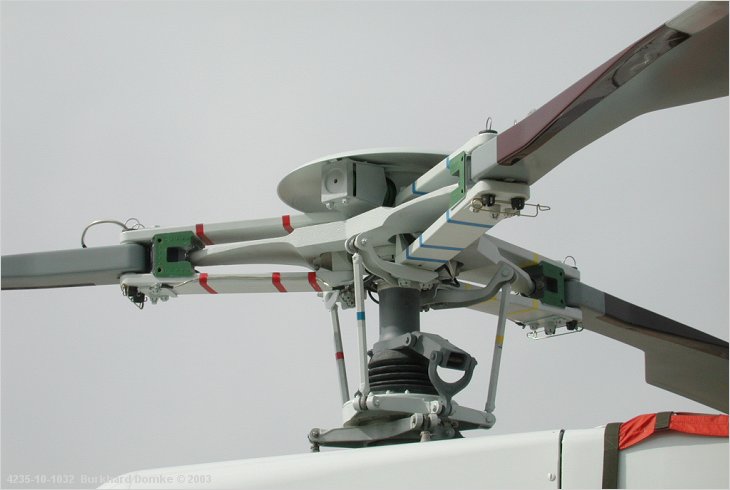
There are various systems. This is a Eurocopter/Aerospatiale StarFlex of some 25-years vintage.
If you look at the rectangular-shaped bits with the colored tape on them sandwiching the blade roots, those we used to call the 'blade grips' (your terminology may vary wherever you live). Their purpose is to hold the blade to the hub. They are permitted motion in the flapping axis and to some degree in the lead-lag axis and to allow the blade to rotate about its axis for desired pitch change (which is why you'll see the pitch change horns attached to them. The two heavy vertical pins go right through the blade root and are secured in place by the nappy pin (no, really).
The star-shaped bit in sandwiched inside there is the 'star'. It is rather flexible, though it doesn't look like it is. It flexes all over the place to allow for coning and pitch changes. It is as close to INflexible as possible in the lead-lag axis. The tip of the star, which you can't really see, is a cylindrical machined bearing surface that plugs into the center of our next bit.
Those squshy-looking green blocks are the 'frequency adaptors'. They are the secret to lead-lag. They permit lead and lag by smushing on their leading and lagging sides (as appropriate) and applying a re-centering force when aerodynamic forces are more equal. All these composite parts need a good going-over now and again to check that the materials aren't breaking down since most of the pieces are completing at least one flexing or bending cycle per turn of the head... lots of potential for fatigue failure.
Works a treat... and... somebody thought of it!
